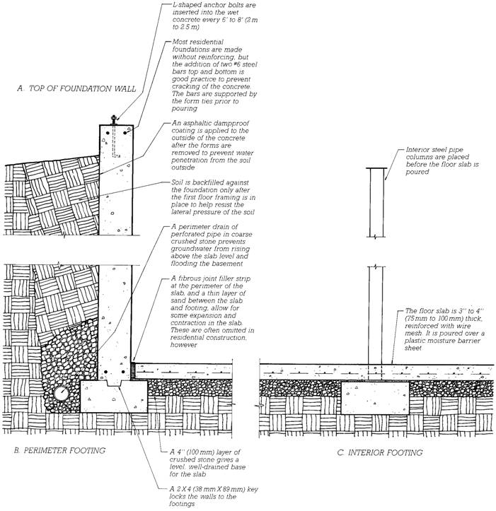
| Foundations for light framing, originally made of stone or brick, are now made in most cases of sitecast concrete or concrete block masonry(Figures 5.5Ð5.11). These materials are highly conductive of heat and usually must be insulated to meet code requirements for energy conservation (Figures 5.8, 5.9, 5.12, and 5.13). Where concrete and masonry construction methods are not practical, such as in extremely cold regions, foundations may be constructed entirely of preservative-treated wood (Figures 5.14 and 5.15). Such permanent wood foundations can be constructed in any weather by the same crew of carpenters that will frame the building; they are readily insulated in the same manner as the frame of the house they support; and they |
easily accommodate the installation of electrical wiring, plumbing, and interior Þ nish materials. Insulating concrete formwork (ICF) foundation systems using permanent insulating forms are easy to construct, eliminate the need for formwork removal, and provide integral insulation (Figure 14.12). Proprietary precast concrete foundation systems relying on factory-fabricated reinforced concrete panels are rapidly erected on site and can be used to construct basement structures of consistent strength and quality. They may be manufactured with insulation integral to the precast panel or designed to readily accept insulation added in the Þ eld.
All basements also need to be carefully dampproofed and drained to avoid ß ooding with groundwater and to prevent the buildup of water pressure in the surrounding soil that could cause the walls to cave in (Figures 5.6, 5.7, and 5.11). |
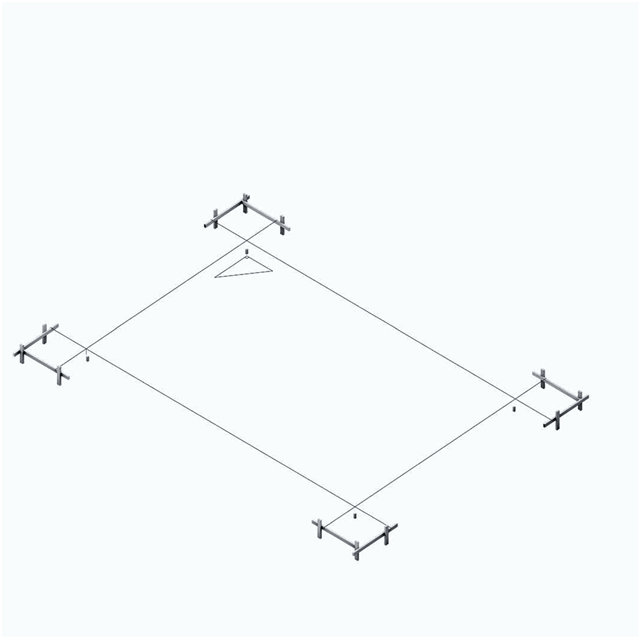
Figure 5.5
Step One in the construction of a simple platform frame building:
establishing the position, shape, and size of the building on the site.
After the corners of the foundation have been staked, batter boards are
erected safely beyond the limits of the excavation area. String lines
crossing over the corner stakes are stretched from the batter boards,
and their positions on the boards are preserved with notches or nails
in the boards. Later, after excavation, the strings are stretched again,
and the foundation corners can be relocated at the bottom of the
excavation. This drawing begins a series of isometric drawings that
will follow the erection of a wood light frame building step by step
throughout the course of this chapter.