
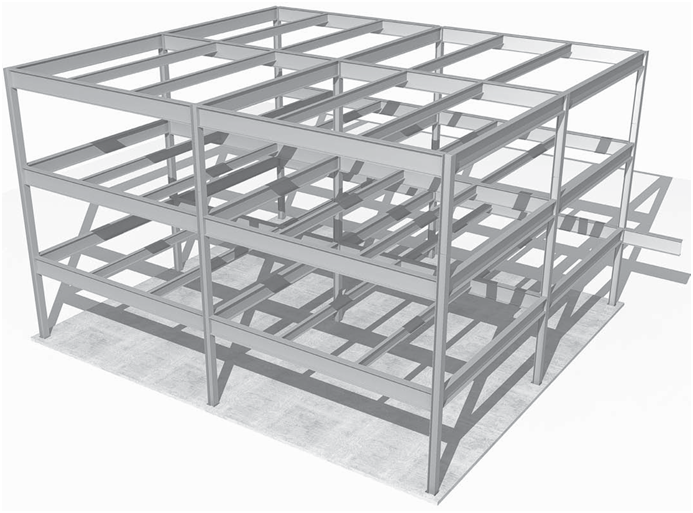
Connection Details of Steel Framing
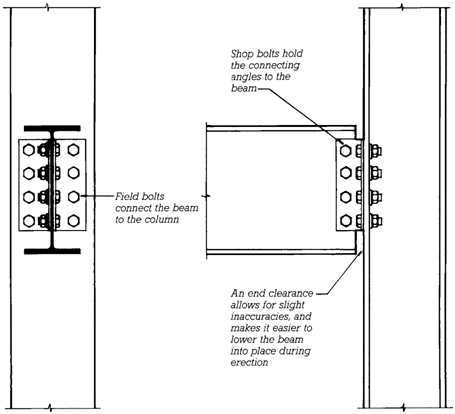
Most steel frame connections use angles, plates, or tees as transitional elements between the members being connected. A simple bolted beam-to column-ß angle connection requires two angles and a number of bolts (Figures 11.24 11.27). The angles are cut to length, and the holes are made in all the components prior to assembly. The angles are usually bolted to the web of the beam in the fabricators shop. The bolts through the ß angle of the column are added as the beam is erected on the construction site. This type of connection, which joins only the web of the beam, but not the ß angles, to the column is known as a shear connection. It is capable of transmitting vertical forces (shear) from a beam to a column.
However, because it does not connect the beam ß angles to the column, it is of no value in transmit ting bending forces (bending moment) from one to the other. To produce a moment connection, one capable of transmitting bending forces between a beam and column, it is necessary to connect the beam ß angles strongly across the joint, most commonly by means of full-penetration groove welds (Figures 11.28 and 11.29).
If the column ß angles are insufficiently strong to accept the forces transmitted from the beam ß angles, stiffener plates must be installed inside the ß angles of the column to better distribute these forces into the body of the column. (Though much less common, it is also possible to design moment transmitting connections that rely solely on bolting.)
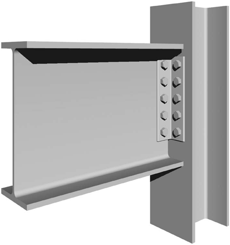
This is a shear connection (AISC simple connection) and not a moment connection, because the flanges of the beam are not rigidly connected to the column. This type of shear connection, in which the beam is connected to the column by angles, plates, or tees fastened to the web of the beam, are also called framed connections.
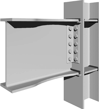
A welded moment connection (AISC Fully Restrained) for joining a beam to a column flange. This is the type of connection that would be used instead of the shear connection at location A in Figure 11.24if a moment connection were required. The bolts hold the beam in place for welding and also provide shear resistance. Small rectangular backup bars are welded beneath the end of each beam flange to prevent the welding arc from burning through. A clearance hole is cut from the top of the beam web to permit the backup bar to pass through. A similar clearance hole at the bottom of the beam web allows the bottom flange to be welded entirely from above for greater convenience. The groove welds develop the full strength of the flanges of the beam, allowing the connection to transmit moments between the beam and the column. If the column flanges are not stiff enough to accept the moments from the beam, stiffener plates are welded between the column flanges as shown here. The flanges of the beam are cut to a “dog bone” configuration to create a zone of the beam that is slightly weaker in bending than the welded con nection itself. During a violent earth quake, the beam will deform permanently in this zone while protecting the welded connection against failure.
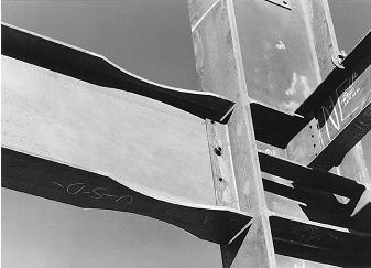
Photograph of a moment connection similar to the one shown in Figure 11.28. The beam has just been bolted to a shear tab that is welded to the column. Next, backup bars will be welded to the column just under the beam flanges, after which the flanges will be welded to the column. (Permission of American Institute of Steel Construction)