
A steel building frame begins as a rough sketch on the drafting board of an architect or engineer. As the build ing design process progresses, the sketch evolves through many stages of drawings and calculations to become a Þ nished set of structural drawings. These show accurate column loca tions, the shapes and sizes of all the members of the frame, and all the loads of the members, but they do not give the exact length to which each member must be cut to mate with the members it joins, and they do not give details of the more routine connec tions of the frame. These are left to be worked out by a subsequent recipient of the drawings, the fabricator.
The Fabricator
The fabricatorÕs job is to deliver to the construction site steel compo nents that are ready to be assembled without further processing. This work begins with the preparation in the fabricatorÕs shop of detailed drawings that show exactly how each piece will be made and what its precise dimen sions will be. The fabricator designs connections to transmit the loads in dicated by the engineerÕs drawings. Within the limits of accepted engi neering practice, the fabricator is free to design the connections to be made as economically as possible, us ing various combinations of welding and bolting that best suit available equipment and expertise. Drawings are also prepared by the fabricator to show the general contractor exactly where and how to install foundation anchor bolts to connect to the col umns of the building and to guide the erector in assembling the steel frame on the building site. When complet ed, the fabricatorÕs shop drawings are submitted to the engineer and the ar chitect for review and approval to be sure that they conform exactly to the intentions of the design team. Mean while, the fabricator places an order with a producer of steel for the stock from which the structural steel mem bers will be fabricated. (The major beams, girders, and columns are usu ally ordered cut to exact length by the mill.) When the approved shop draw ings, with corrections and comments, are returned to the fabricator by the design team, revisions are made as necessar y, and full-size templates of cardboard or wood are prepared as required to assist the shop workers in laying out the various connections on the actual pieces of steel.
Plates, angles, and tees for connec tions are brought into the shop and cut to size and shape with gas-fueled cutting torches, power shears, and saws. With the aid of the templates, bolt hole locations are marked. If the plates and angles are not unusually thick, the holes may be made rapidly and economically with a punching machine. In ver y thick stock, or in pieces that will not Þ t conveniently into the punching machines, holes are drilled rather than punched.
Pieces of steel stock for the beams, girders, and columns are brought into the fabricatorÕs shop with an overhead traveling crane or conveyor system. Each piece is sten ciled or painted with a code that tells which building it is intended for and exactly where it will go in the build ing. With the aid of the shop draw ings, each piece is measured and marked for its exact length and for the locations of all holes, stiffeners, connectors, and other details. Cut ting to length, for those members not already cut to length at the mill, is done with a power saw or a ß ame cutting torch. The ends of column sections that must bear fully on base plates or on one another are squared and made perfectly ß at by sawing, milling, or facing. In cases where the columns will be welded to one another, and for beams and girders that are to be welded, the ends of the ß anges are beveled as necessar y. Beam ß anges are coped as required. Bolt holes are punched or drilled (Figure 11.43). Plasma (high-temper ature ionized gas) cutting and laser
|
|
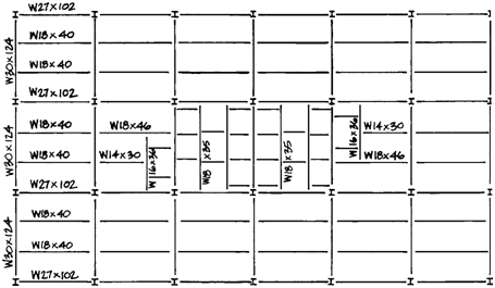
Figure 11.42 A typical framing plan for a multistory steel-framed building, showing size des ignations for beams and girders. Notice how this frame requires beam-to-column flange connections where the W30 girders meet the columns, beam-to-column-web connections where the W27 beams meet the columns, and coped beam-girder connections where the W18 beams meet the W30 girders. The small squares in the middle of the building are openings for elevators, stairways, and mechani cal shafts. An architect’s or engineer’s framing plan would also give dimensions between centers of columns, and would indicate the magnitudes of the loads that each joint must transfer, to enable the fabricator to design each connection. |
cutting are also Þ nding increased use in steel fabrication. Both of these types of cutting devices can be driven by machines that allow the fully auto mated cutting and shaping of parts from digitally prepared models.
Where called for, beams and gird ers are cambered (cur ved slightly in an upward direction) so that they will de ß ect into a straight line under load. Cambering may be accomplished by a hydraulic ram that bends the beam enough to force a permanent defor mation. Steel shapes can also be bent to a smooth radius with a large ma chine that passes the shape through three rollers that ß ex it sufÞ ciently to impart a permanent cur vature (Figure
11.44). An older, much more costly means of cambering involves heating local areas of one ß ange of the mem ber with a large oxyacetylene torch. As each area is heated to a cherr y-red color, the metal softens, expands, and deforms to make a slight bulge in the width and thickness of the ß ange be cause the surrounding steel, which is cool, prevents the heated ß ange from lengthening. As the heated ß ange cools, the metal contracts, pulling the member into a slight bend at that point. By repeating this process at sev eral points along the beam, a camber of the desired shape and magnitude is produced.
As a last step in fabricating beams, girders, and columns, stiffen er plates are arc welded to each piece as required, and connecting plates, angles, and tees are welded or bolted at the appropriate locations (Figure
11.45). As much connecting as pos sible is done in the shop, where tools are handy and access is easy. This saves time and money during erec tion, when tools and working condi tions are less optimal and total costs per worker-hour are higher.
Plate girders, built-up columns, trusses, and other large components are assembled in the shop in units as large as can practically be transported to the construction site, whether by truck, railway, or barge (Figure 1 1.46). Intricate assemblies such as large
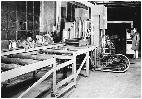 |
Figure 11.43 Punching bolt holes in a wide-flange beam. (Courtesy of W. A. Whitney Corp.)
|
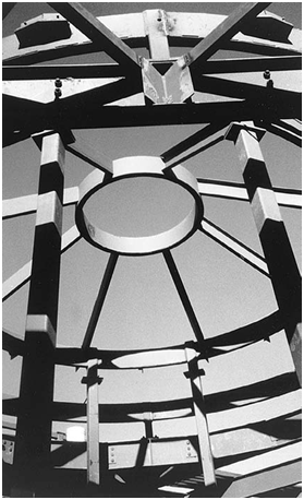 |
Figure 1.44 Rectangular hollow structural sections for this frame were bent into curves by the fabrica tor. Wide-flange shapes can also be bent. (Photo by Eliot Gold- stein, The Goldstein Partnership, Architects) |
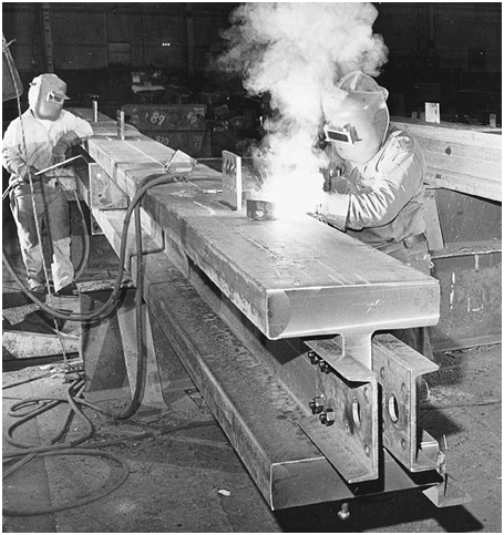 |
Welders attach connector plates to an exceptionally heavy column section in a fabricator’s shop. The twin channels bolted to the end of the column will be used to attach a lifting line for erection, after which they will be removed and reused. (Courtesy of U.S. Steel Corp.) |

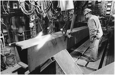 |
Figure 11.46 Machine welding plates together to form a box column. The torches to the left preheat the metal to help avoid thermal distortions in the column. Mounds of powdered flux around the electrodes |
trusses are usually preassembled in their entirety in the shop, to be sure that they will go together smoothly in the Þ eld, then broken down again into transportable components.
As the members are completed, each is straightened, cleaned and prime painted as necessar y, and in spected for quality and for confor mance to the job speciÞ cations and shop drawings. The members are then taken from the shop to the fab ricatorÕs yard by crane, conveyor, trol ley, or forklift, where they are orga nized in stacks according to the order in which they will be needed on the building site.
As an alternative to the tradi tional process in which the fabricator produces the Þ nal design for the steel connections and submits these designs for review by the structural engineer, a structural engineer may use three-di mensional modeling software to de sign the steel connections and supply digital data to the fabricator to drive the fabricatorÕs automated equip ment. While this method requires the engineer to assume more responsi bility for the Þ nal design of the steel connection details, it also can shorten the time required for steel to arrive on site and can improve the coordination between the structural steel and other building systems.
Thanks for any other informative blog. Where else could I am getting that type of info written in such a perfect manner?
I have a project that I am just now operating on, and I’ve been on the glance out for such info.
When I originally left a comment I appear to have clicked on the -Notify me when new comments are added- checkbox and
from now on whenever a comment is added I get 4 emails with the
exact same comment. Is there an easy method you can remove
me from that service? Many thanks!