
|
A blueprint is a type of paper-based reproduction usually of a technical drawing documenting an object, an architecture or engineering design. The term is now generally used to refer to any detailed plan of a building or object. Blueprints have for thousands of years provided a universal language by which design and construction information is transmitted to the builder, engineer, craftsperson, designer, and others. Blueprint reading therefore refers to the process of interpreting a drawing. An accurate mental picture of the object upon completion can be formulated from the information provided. While originally blueprints did have a blue background with white lines (as a result of the process used to produce them), subsequent improvements to the copying process involved ammonia and coated papers that react to light. Additional improvements eliminated the ammonia process, leading up to today’s prints. Blueprints are today usually white pages with black or blue lines. Nonetheless, the term has remained with us and probably will remain in use for a long time to come. You may also hear blueprints referred to as drawings, prints, or plans. A blueprint is a representation of what is to be constructed. It is a drawing of what is to be built. Blueprints, however, are very precise drawings that are exact representations of what is to be built. Obviously, they are drawn much, much smaller than the proposed structure, but they are exact and detailed. Every line on a construction drawing is carefully placed. The relation of a line to another line shows distance. Blueprints are critical forms of communication that provide a great deal of information. If the prints are not clear enough to read and use, wait until you have better ones or make your own. Otherwise you may encounter serious problems in the course of the project. Use your judgment. Drawings have little value if they cannot be satisfactorily reproduced. Sets of prints must be provided to building departments (for approvals), as well as to contract bidders, estimators, subcontractors, and others who are concerned with the construction of the proposed building. Original drawings are typically retained by the consultant. There are several methods of making prints; these are discussed below. |
|||
| Copyright © 2009 by The McGraw-Hill Companies, Inc. Click here for terms of use. | 1 | ||
| 2 | Chapter 1 | ||
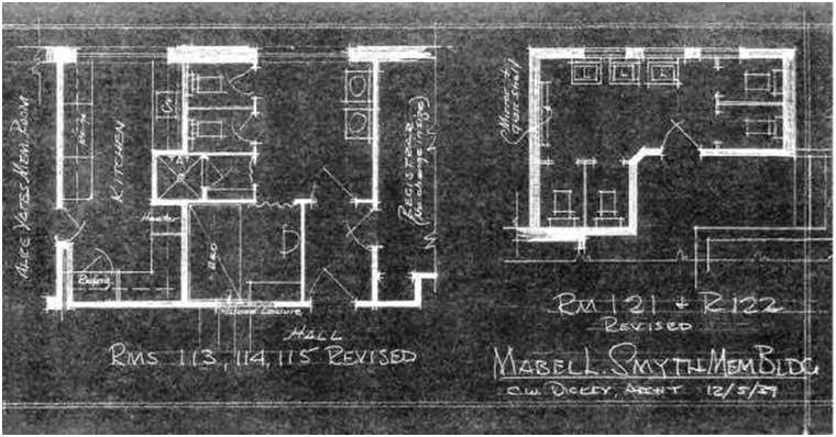
| 1.2 PRINT BASICS As previously mentioned, a blueprint was originally a print comprising a dark blue background with white lines (Figure 1.1). Traditional blueprints have largely been replaced by more modern, less expensive printing methods and digital displays. Indeed, today over 95 percent of businesses are producing prints generated with computer-aided drafting (CAD) software and printed on large printers. The most common methods used to reproduce drawings are outlined below: |
|||
| Diazo-Print Process In the early 1940s, cyanotype blueprints began to be supplanted by diazo prints or whiteprints, which have blue lines on a white background. These drawings are also known as Ozalid or blue-line prints. The diazo process is an inexpensive method of making prints from any type of translucent material. It is the result of a printing process that utilizes ultraviolet light passing through a translucent original drawing to expose a chemically coated paper or print material underneath. As the light does not pass through the lines of the drawing, the chemical coating beneath the lines remains unexposed. The print material is then exposed to ammonia vapor, which activates the remaining chemical coating to produce the blue lines. Diazo prints can also be produced with black or sepia lines. |
|||
 |
|||
| Figure 1.1 Illustration of traditional blueprint. | |||
| Blueprint Standards | 3 | ||
|
While modern advances in replication technology have allowed other techniques to replace the traditional blueprint, some businesses continue to maintain this process. In most cases the diazo process (which is an environmentally friendly process) has been replaced by xerographic print processes similar to standard copy-machine technology using toner on bond paper. Plain-Paper Copies This process uses plain-paper machines; prints can be made from opaque originals, whereas diazos require translucent originals. Plain-paper copiers are mainly used in offices where changes and modifications are needed during the development stages or where the originals need to be put on vellum or film, from which volume prints are made for distribution using the less expensive diazo process. This method is especially useful in printing CAD plots done on bond paper (Figure 1.2). Plain-paper copiers are also effective in making copies from shop-worn originals onto durable polyester film or vellum media. Some copiers can also enlarge or reduce the size of the original drawing. |
|||
| Photocopy Process The photocopy process is gaining extensive use for copying engineering and architectural drawings. With this method a picture of the original drawing is used to then produce as many prints as required, similar to a Xerox or other copying machines. This type of copier also has the added advantage of making reductions or enlargements of the original drawing. These copy machines in fact very much resemble the copiers found in the traditional office environment. The main difference is the capacity to copy large drawings. The increasing popularity of these machines is due mainly to the use of ordinary paper that does not require coating and avoids the possible hazards of ammonia. |
|||
| Photographic Reproduction Various types of photographic reproduction are available that provide greater accuracy and detail, making them easier to read, correct, and reprint. Photostats can be made from an original drawing by using a large, specially designed camera that produces enlargements or reductions from the original work. This direct print process delivers a negative with white lines and a dark background. A number of high-quality reproduction methods such as microfilming are available that use a film negative made from the original drawing. Projection prints from a photographic negative can be reproduced on matte paper, glossy paper, vellum, and Mylar (Cronoflex™). These excellent-quality prints can be enlarged or reduced in scale with accuracy and are very durable. To microfilm a drawing, one must first convert the original drawing to a microfilm frame using a special microfilm-processing camera mounted on a frame over a platform. The camera reduces the drawing in order to fit on the microfilm; the reduction can be varied by changing the height of the camera above the drawing. After the film is developed, the negative is typically mounted on a standard-size aperture or data card and is systematically filed for future retrieval. A microfilm-enlarger reader-printer with a display screen is normally used to review the images as well as reproduce print copies of various sizes from the negative. Microfilming is also an excellent means of storing drawings, thus eliminating the need to retain cumbersome original tracings (Figure 1.3). |
|||
| 4 | Chapter 1 | ||
 |
|||
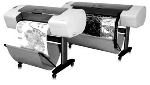
| Figure 1.2 HP Designjet T610 blueprint plotter for printing CAD and GIS projects (courtesy, Hewlett-Packard Development Company, L.P.). | |||
 |
|||
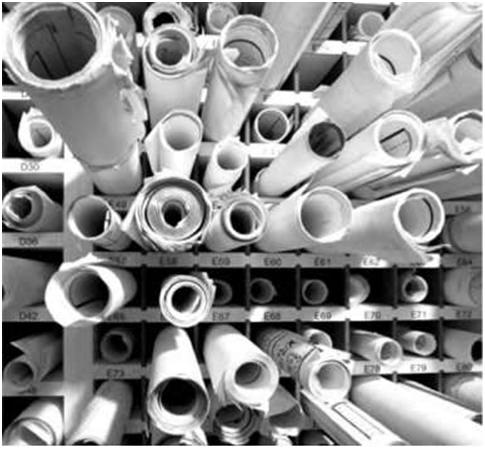
| Figure 1.3 Storage of blueprint paper drawings can be very cumbersome and space-consuming. | |||
| Blueprint Standards | 5 | ||
| Multicolor Offset Prints Sometimes prints are produced in several colors (usually blue and red) via offset printing. Typically the original drawings are made in smaller scales and sizes for further economy. The various colors are used to highlight new work in relation to existing construction or to display complex mechanical or electrical systems in new projects. The main advantage to the use of colors is in facilitating the reading of the drawings, resulting in fewer mistakes and requiring less time in interpreting them. More recently, designs created using computer-aided-design techniques may be transferred as a digital file directly to a computer printer or plotter; in some applications paper is avoided altogether and work and analysis are done directly from digital displays. Even as print and display technology advances, the traditional term “blueprint” continues to be used informally to refer to each type of image. Computer-Aided Design and Drafting Computer-aided design (CAD) has brought a new innovation to the field of engineering design and is discussed in greater detail in Chapter 2. CAD is used to design, develop, and optimize the process to make a clean, clear, computer-generated construction drawing, accurately drafted as per specified dimensions. CAD has turned out to be an invaluable technology with great benefits, such as lower product-development costs, faster processing, and a greatly shortened design cycle. It is a technology that permits the consultant to focus on the business of design instead of wasting time searching for and redrawing old documents. CAD drawings can be generated from most formats including hand-drawn documents, tiff files, or any other image files that can be converted to a .dwg file using AutoCAD or other CAD software. 1.3 BASIC DRAFTING STANDARDS AND STANDARDS-SETTING ORGANIZATIONS |
|||
|
In the United States, the American National Standards Institute (ANSI) and the International Organization for Standardization (ISO) have adopted drafting standards that are voluntarily accepted and widely used throughout the world. These standards incorporate and complement other architectural/engineering standards developed and accepted by professional organizations such as the American Institute of Architects (AIA), the American Society of Mechanical Engineers (ASME) and others. Some large firms have adopted their own standards to suit their individual needs. ANSI Standards for Blueprint Sheets Most architectural-drafting offices in the United States use ANSI standard sheet sizes as shown in Table 1.1. ANSI Y14.2, Y14.3, and Y14.5 are the standards that are commonly used in the U.S.: 1. In the U.S. letter-size paper is an architectural (first series) A-size sheet. It is 8.5 x 11 inches. An engineer’s (second series) A-size sheet is 9 x 12 inches. 2. B-size sheets are double the size of A sheets (11 x 17—also called tabloid—or 12×18 inches). 3. C-size sheets are double the size of B sheets (17 x 22 or 18 x 24 inches). 4. D-size sheets are double the size of C sheets (22 x 34 or 24 x 36 inches), and so on. |
|||
| 6 | Chapter 1 | |||||||||||||||||||||||||||||||||||||||||||||||||||||||||||||||||||||||||||||||||||||||||||||||||
| Table 1.1 ANSI (American National Standards Institute) standard recommended sheet sizes. | ||||||||||||||||||||||||||||||||||||||||||||||||||||||||||||||||||||||||||||||||||||||||||||||||||
|
||||||||||||||||||||||||||||||||||||||||||||||||||||||||||||||||||||||||||||||||||||||||||||||||||
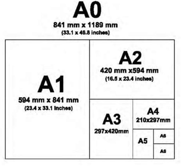
| ISO Standards The metric drawing sizes correspond to international paper sizes, in Europe and many other countries ISO (International Standards Organization) metric measurements are used (Table 1.1). The ISO defines a set of standard metric line widths for drafting. For example, the ISO A series of sheet sizes is based on a constant width to length ratio of 1: \f2. Thus, each smaller sheet size is exactly half the area of the previous size, so that if we cut an A0 sheet in half, we get two A1 sheets; if we cut an A1 sheet in half, we get two A2 sheets; and so on. In Figure 1.2 the A0 size is defined as having an area of 1 square meter. This lets us express paper weights in grams per square meter. The relationship of 1: \J2 is particularly important for reduction onto microfilm or reduction and enlargement on photocopiers. Metric equipment including microfilm cameras, microfilm printers, photocopiers, as well as drawing pen sizes are designed around this ratio. This simplifies the process of archiving drawings, resizing, and modifying drawings. Like the ISO A-series sheet sizes, the pen sizes increase by a factor of two, which allows additions and corrections to be made on enlargements or reductions of drawings. Each width is assigned a color code. The color code corresponds to that for the matching lettering stencil. Line widths and color codes are standardized across all manufacturers. |
||||||||||||||||||||||||||||||||||||||||||||||||||||||||||||||||||||||||||||||||||||||||||||||||||
| Other Standard-Setting Organizations As previously mentioned, ANSI and ISO are the two main drafting-standard-setting bodies. However, there are other organizations that have developed engineering standards that complement these. Like |
||||||||||||||||||||||||||||||||||||||||||||||||||||||||||||||||||||||||||||||||||||||||||||||||||
| Blueprint Standards | 7 | ||
 |
|||
| Figure 1.4 Diagram showing ISO (International Standards Organization) metric sheet sizes. | |||
|
the ANSI, the American Society of Mechanical Engineers (ASME) has standardized drawing-sheet sizes that are designated by letter and published in MIL-STD-100A. ASME also published the ASME Y14.5M-1994 Dimensioning and Tolerancing standard. Other standard-setting organizations include the American Institute of Architects (AIA), the Canadian Standards Association (CSA), the American Welding Society (AWS), and others. Moreover, some large firms have adopted their own standards to suit their individual needs. In the final analysis, the drawing-sheet sizes you use are determined by the needs of your employer or client and your need to economically lay out required information. |
|||
Part 6 of this article does not show the right side of its text or tables there in
Great topic.
I needs to spend some time studying more or working out more.
Thank you for excellent information I used to be in search of this information for my mission.