
| 5.1 INTRODUCTION | |||
|
Drawings are the main vehicle of communication in the construction industry, and in learning to read and interpret blueprints, it is necessary to develop the ability to visualize the object to be built. Orthographic projection principles are basic to all fields in the construction industry. In order to be capable of interpreting a drawing, one must be able to relate the different views. It is often not possible to read a blueprint by looking at a single view; two or three views may be needed to correctly read and visualize the form. Figure 5.1 shows three example of objects requiring only two views to read. Figure 5.2 shows a drawing using three views. Whether sketching or drawing, the objective is the same. The goal is to communicate the necessary detail to the targeted audience, whether it is the builder, manufacturer, or client. Without the ability to communicate, architects, and engineers cannot function in a team. Competency in drawing and sketching are essential communication tools for architects, engineers, and those involved in the building trades and manufacturing industries. In the interpretation of complex objects, even three drawings are not usually adequate to convey all the necessary information. Additional special views may be required, including pictorials, auxiliary views, sections, and exploded views. A view of an object is technically known as a projection. Pictorials are an ancillary category within orthographic projection. Pictorials show an image of an object as viewed from a skew direction in order to reveal all three directions (axes) of space in one picture. Orthographic pictorial instrument drawings are often used to approximate graphical perspective projections, but there is attendant distortion in the approximation. Because pictorial projections innately have this distortion, great liberties are often taken for economy of effort and best effect. Pictorials are discussed later in this chapter. 5.2 ORTHOGRAPHIC (MULTIVIEW) DRAWINGS AND PROJECTIONS |
|||
| For many years architects and engineers have utilized a system known as orthographic projection to accurately represent three-dimensional objects graphically on paper. In recent years the term “multiview | |||
| Copyright © 2009 by The McGraw-Hill Companies, Inc. Click here for terms of use. | 71 | ||
| 72 | Chapter 5 | ||
 |
|||
| 0 Diameter Figure 5.1A An example of a simple drawing of objects that essentially requires only two views to read. |
|||
 |
|||
| Figure 5.1B An example of a simple drawing of objects that essentially requires only two views to read. | |||
| Types of Views | 73 | ||
 |
|||
| Figure 5.1C An example of a simple drawing of objects that essentially requires only two views to read. | |||
 |
|||
| FRONT VIEW SIDE VIEW Figure 5.2 A drawing of an object requiring three views to interpret correctly. |
|||
| 74 | Chapter 5 | ||
|
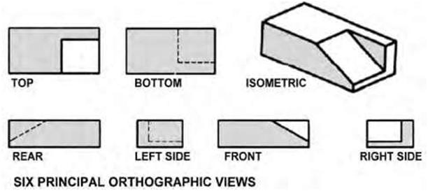
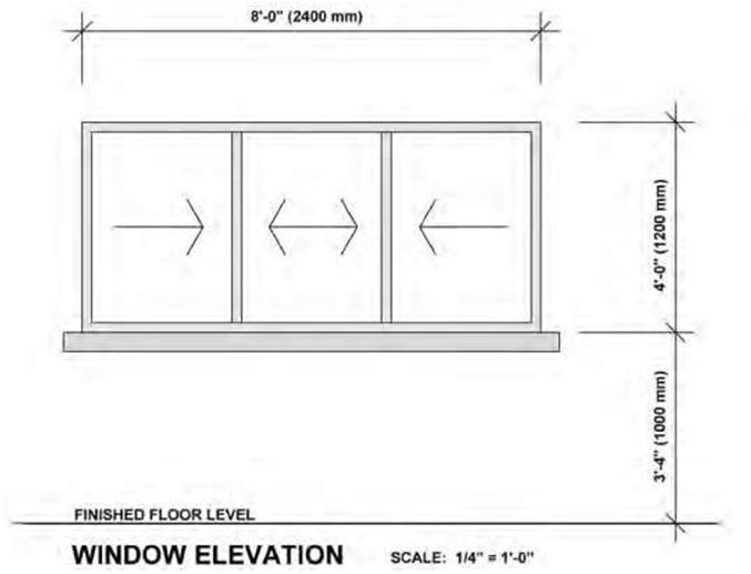
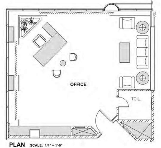
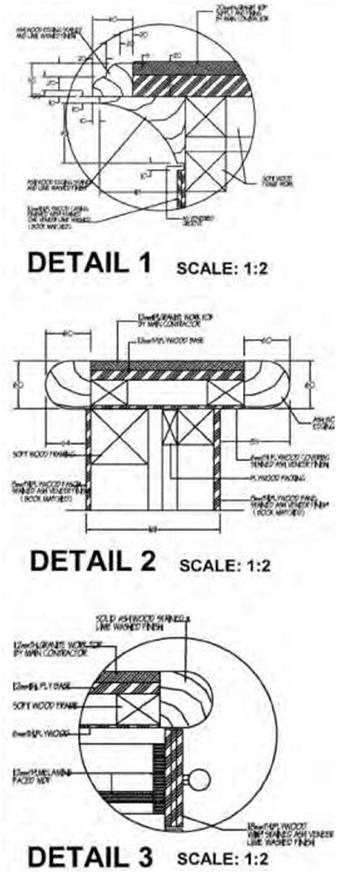
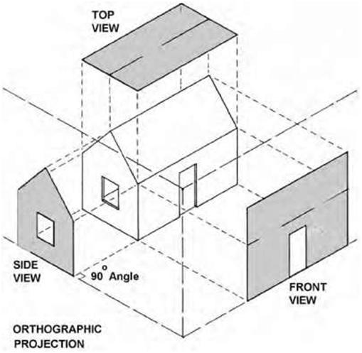
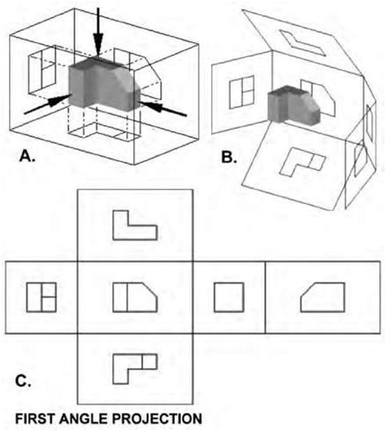
drawing” has come into general use, indicating that more than one view is used to illustrate an object, but the terms are essentially synonymous. “Orthographic” comes from the Greek word for “straight writing (or drawing).” Orthographic projection shows the object as it looks from the front, right, left, top, bottom, or back, and different views are typically positioned relative to each other according to the rules of either first-angle or third-angle projection. Ortho views depict the exact shape of an object seen from one side at a time as you are looking perpendicularly to it without showing any depth. A single view of an object is rarely adequate to show all necessary features. Figure 5.3 is an example of orthographic projection showing the six principal views used by architects and engineers in construction and industrial drawings. Common types of orthographic drawings include plans, elevations, and sections. The most obvious attribute of orthographic drawing is its constant scale—that is, all parts of the drawing are represented without foreshortening or distortion, retaining their true size, shape, and proportion. Thus, in an orthographic drawing, a window shown to be 8 feet wide by 4 feet high will always be drawn at this size, no matter how far it is from our viewpoint (Figure 5.4). Plans are really orthographic views of an object as seen directly from above. Floor plans are the most common form of plan; they delineate the layout of a building. A floor plan is represented by a horizontal section taken through the building or portion of a building just above the windowsill level. In addition to the arrangement of rooms and spaces, floor plans need to show the location of various architectural elements such as stairs, doors, and windows and details such as wall and partition thickness. Generally, the greater the scale of a drawing, the more detail that it is expected to contain (Figure 5.5). Thus, a drawing at a scale of 1/4″ = 1’0″ will typically contain more information and show more detail than a drawing at a 1/8″ = 1’0″ scale. Likewise, a scale of 1:2 is greater than that of 1/4 inch = 1 foot, 0 inches. Other types of plans used in building construction may include site plans, which typically show the layout of a site; foundation plans. which show the building structure; and reflected ceiling plans, which are normally used to locate light fixtures and design features. Two important rules that must be adhered to in orthographic drawing are the placement and alignment of views, depending on the type of projection to be used. These rules are discussed below. In addition, projection lines between the views must be aligned horizontally and vertically. Orthographic (multiview) projection is a generally accepted convention for representing three-dimensional (3D) objects using multiple dimensions (2D) of the front, top, bottom, back, and sides of the object. In practice, the minimum number of views possible is used to describe all the details of the object. Usually, a front view, top, and single side view are sufficient and are oriented on the paper according to accepted convention. Figure 5.6 represents a multiview projection for a simple house. The projection clearly shows that it is a form of parallel projection, and the view direction is orthogonal to the projection plane. Isometric projection attempts to represent 3D objects using a single view. Instead of the observer viewing the object perpendicular to it, the object is rotated both horizontally and vertically relative to the observer. There are rules and conventions to guide the creation of both types of projections. Additionally, either of them can be supplemented with various types of dimensions. First-Angle Projection First-angle projection is the ISO standard and is used mostly in Europe and Asia. If we imagine projecting a 3D object into a transparent plastic cube, the main object surfaces are projected onto the cube’s walls so that the top view is placed under the front view and the right view is placed at the left of the front view, a two-dimensional representation of the object is formed by “unfolding” the box and viewing all of the interior walls as is shown in Figure 5.7A. |
|||
| Types of Views | 75 | ||
 |
|||
| Figure 5.3 An illustration of an object showing the six principal views in orthographic projection based on third-angle projection. | |||
 |
|||
| Figure 5.4 An elevation of a window drawn in an orthographic format retaining its true size, shape, and proportion and showing no distortion or foreshortening. | |||
| 76 | Chapter 5 | ||
 |
|||
| Figure 5.5A Design drawing plan of an office space drawn to a scale of 1/4 inch = 1 foot, 0 inches. Notice that there are no dimensions as would be found in a typical orthographic working drawing. | |||
|
In first-angle projection, the object lies above and before the viewing planes; the planes are opaque; and each view is pushed through the object onto the plane furthest from it. Extending to the six-sided box, each view of the object is projected in the direction of sight of the object onto the interior walls of the box; that is, each view of the object is drawn on the opposite side of the box. |
|||
| Types of Views | 77 | ||
 |
|||
| Figure 5.5B Counter detail drawing to a scale of 1:2. This drawing is to a greater scale and has more detail than the ¼ inches = 1 foot, 0 inches drawing. | |||
| 78 | Chapter 5 | ||
 |
|||
| Figure 5.6 A multiview projection for a simple house. This is the format most used by architects and engineers. | |||
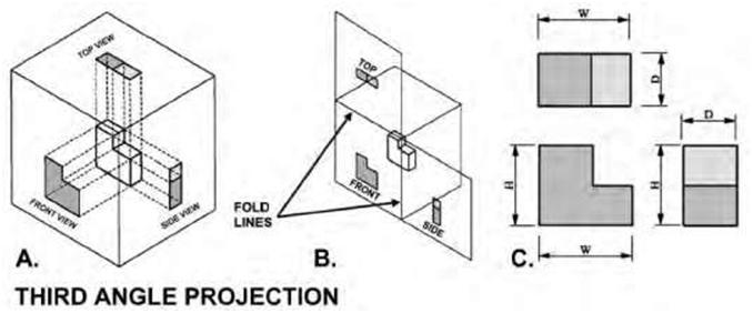
| Third-Angle Projection In third-angle projection the left view is placed on the left and the top view is placed on the top (Figure 5.7 B and C). This type of projection is primarily used in the United States and Canada. It should be noted that not all views are necessarily used, and determination of which surface constitutes the front, back, top, and bottom varies depending on the projection used. In third-angle projection, the object lies below and behind the viewing planes. The planes are transparent, and each view is pulled onto the plane closest to it. Using the six-sided viewing box, each view of the object is projected opposite to the direction of sight onto the exterior walls of the box; that is, each view of the object is drawn on the same side of the box. The box is then unfolded to view all of its exterior walls, as shown in Figure 5.7C. |
|||
| Types of Views | 79 | ||
 |
|||
| Figure 5.7A Views of an object being projected according to first-angle projection which is the ISO standard and is primarily used in Europe and Asia (source: Wikimedia Commons). | |||
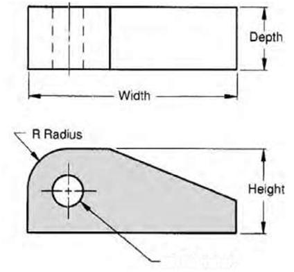
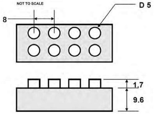
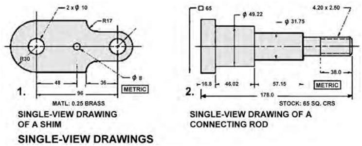
| Single-View Drawings One-view drawings are commonly used in the manufacturing industry to represent parts that are uniform in shape. These drawings are often supplemented with notes, symbols, and written information. They are normally used to describe the shape of cylindrical, cone-shaped, rectangular, and other symmetrical parts. Leaders are often used to relate a note to a particular feature, as in Figure 5.8. Thin, flat objects of uniform thickness are typically represented by one-view drawings. |
|||
| 80 | Chapter 5 | ||
 |
|||
| Figure 5.7B Examples of third angle projection that is primarily used in the United States and Canada. This type of projection produces two plan views and four side views. In third angle projection the left view is put on the left and the top view on the top. | |||
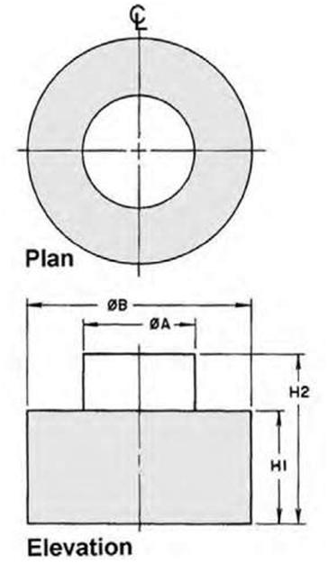
| Two-View Drawings Simple, symmetrical flat objects and cylindrical parts, such as sleeves, shafts, rods, or studs, require only two views to show the full details of construction. The two views usually include the front view and either a right side or left side view or a top or bottom view. |
|||
| Types of Views | 81 | ||
 |
|||
|
Figure 5.7C More examples of third angle projection that is primarily used in the United States and Canada. This type of projection produces two plan views and four side views. In third angle projection the left view is put on the left and the top view on the top. |
|||
 |
|||
| Figure 5.8 Two examples of single-view drawings, which are commonly used in industry to represent parts that are uniform in shape. | |||
| 82 | Chapter 5 | ||
|
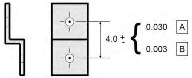
Features on both sides of a centerline shown on a drawing are the same size and shape. These equal-length short, parallel lines are placed outside the drawing of the object on its centerline (Figure 5.9). A hidden detail may be straight, curved, or cylindrical. Whatever the shape of the detail and regardless of the number of views, it is represented by a hidden edge or invisible edge line. Three-View Drawings Regularly shaped flat objects that require only simple machining operations may often be adequately described with notes on a one-view drawing. However, when the shape of the object changes, portions are cut away, or complex machining or fabrication processes must be shown, the single view would normally be inadequate to describe the object accurately. The combination of front, top, and right side views represents the method most commonly used by drafters to describe simple objects (Figure 5.10). For building construction, other views would typically be needed. The Front View Before an object is drawn, it is examined to determine which views will best furnish the information required to construct the object. The surface shown as the observer looks at the object is called the front view. To draw this view, the drafter goes through an imaginary process of raising the object to eye level and turning it so that only one side can be seen. If an imaginary transparent plane is placed between the eye and the face of the object and parallel to the object, the image projected on the plane is the same as that formed in the eye of the observer. The Top View To draw a top view, the drafter goes through a process similar to that required to obtain the front view. However, in third-angle projection, instead of looking squarely at the front of the object, the view is seen from a point directly above it. When a horizontal plane on which the top view is projected is rotated so that it is in a vertical plane, the front and top views are in their proper relationship. In other words, the top view is always placed immediately above and in line with the front view. The Side View A side view is developed in much the same way that the other two views were obtained. That is, the drafter imagines the view of the object from the side that is to be drawn and then proceeds to draw the object as it would appear if parallel rays were projected upon a vertical plane. Three-Dimensional Graphics Depicting three dimensions on a flat piece of paper is a very important skill for designers, enabling them to communicate their ideas to other people. This is especially useful when showing your design to non-professionals such as managers and marketing personnel. There are several tried and tested three-dimensional drawing systems used to produce a realistic representation of an object. Some techniques, such as isometric projection, are based on mathematical systems; others try to convey a larger degree of realism by applying perspective to the drawing. Amongst the methods covered in this tutorial are oblique, isometric, axonometric, and perspective drawing. |
|||
| Types of Views | 83 | ||
 |
|||
| Figure 5.9 Two-view drawings are used mainly for simple, symmetrical flat objects and cylindrical parts. The views usually include a front view and either a right or left side view or a top or bottom view. | |||
| 5.3 PROJECTION SYMBOLS | |||
|
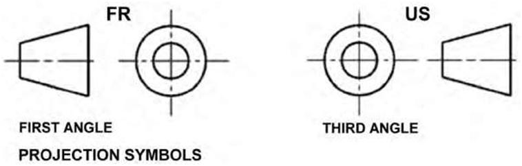
The International Organization for Standardization (ISO) recommends the incorporation of projection symbols on drawings that are produced in one country for use in many countries (Figure 5.11). The projection symbols are intended to promote the accurate exchange of technical information through drawings. |
|||
| 84 | Chapter 5 | ||
 |
|||
| Figure 5.10 Three-view drawings are typically required for more complex shapes. The combination of front, top, and right side views reflects the method normally used by drafters to describe these objects. | |||
 |
|||
| Figure 5.11 The ISO projection symbols indicate whether a first-angle or third-angle projection is being used in a drawing. | |||
| Types of Views | 85 | ||
|
As mentioned earlier, the United States and Canada use the third-angle system of projection for drawings, whereas other countries use a different system known as first-angle projection. The purpose of introducing the ISO projection symbols is to indicate that there is a continuously increasing international exchange of drawings for the production of interchangeable parts. Thus, the symbol indicates whether the drawing follows the third- or first-angle projection system. The ISO projection symbol, the notation on tolerances, and information on whether metric and/or inch dimensions are used on the drawing should appear as notes either within the title block or adjacent to it. The designation of projection type is not always included with the symbol on a drawing. It is rarely used on architectural drawings but is usually included on engineering drawings. When drawings are transferred from one convention to another, considerable confusion is encountered in drafting rooms and engineering departments. On engineering drawings, the projection angle is denoted by an international symbol consisting of a truncated cone, respectively, for first-angle and third-angle and whether the cone is to the right or left of the two concentric circles symbol. The 3D interpretation of the symbol can be deduced by envisioning a solid truncated cone standing upright with its large end on the floor and the small end upward. The top view is therefore two concentric circles (“doughnut”). In particular, the fact that the inner circle is drawn with a solid line instead of dashed lines designates this view as the top view, not the bottom view. Both first-angle and third-angle projections result in the same six views; the difference between them lies in their arrangement around the box. 5.4 OBLIQUE DRAWINGS |
|||
|
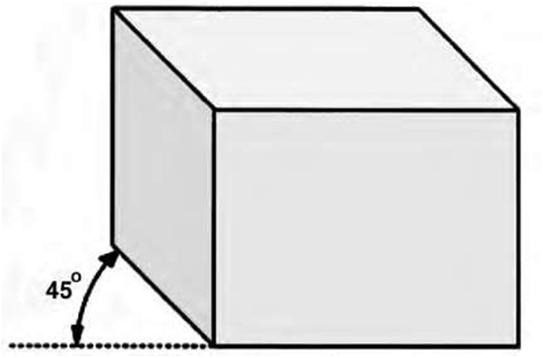
Oblique projection is a simple form of parallel graphical projection used mainly for producing pictorial, two-dimensional images of three-dimensional objects. Oblique drawings are similar to isometrics except that the front view is shown in its true shape on the horizontal line—i.e., when drawing an object in oblique, the front view is drawn flat (Figure 5.12). Thus, it projects an image by intersecting parallel rays from the three-dimensional source object with the drawing surface. In oblique projection (as in orthographic projection), parallel lines from the source object produce parallel lines in the projected image. The projectors intersect the projection plane at an oblique angle to produce the projected image, as opposed to the perpendicular angle used in orthographic projection. A 45-degree angle is the most commonly used to draw the receding lines from the front view, but other angles are acceptable. In an oblique sketch, circular lines that are parallel to the frontal plane of projection are drawn at their true size and shape. Hence, circular features appear as circles and not as ellipses. This is the main advantage of the oblique sketch. The three axes of the oblique sketch are drawn at the horizontal, vertical, and a receding angle that can vary from 30 to 60 degrees. Whereas an orthographic projection is a parallel projection in which the projectors are perpendicular to the plane of projection, an oblique projection is one in which the projectors are not perpendicular to the plane of projection. With oblique projection all three dimensions of an object can be shown in a single view. Oblique drawing is a primitive form of 3D drawing and the easiest to master. It is not a true 3D system but a two-dimensional view of an object with contrived depth. Instead of drawing the sides full size, they are only drawn at half the depth, creating a suggested depth that adds an element of realism to the object. Even with this contrived depth, oblique drawings look very unconvincing to the eye. In Figure 5.13 the side views are drawn at a 45-degree angle. In oblique projection the side views are typically fore- |
|||
| 86 | Chapter 5 | ||
 |
|||
| Figure 5.12 Technique for producing an oblique drawing. The front view is shown in its true form on the horizontal line and should be drawn flat. | |||
|
shortened to provide a more realistic view of the object. To foreshorten the side views, the object’s side measurements are normally halved. In this case, the sides are 50 mm (2 inches) long, but they have been drawn at 25 mm (1 inch). Because the oblique drawing is not realistic, it is rarely used by professional architects and engineers. 5.5 AUXILIARY VIEWS |
|||
|
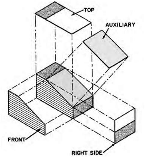
Occasionally we find surfaces or features on drawings that are oblique to the principal planes of projection and still are shown in their true shape. Other features in modern construction are also designed at various angles to the principal planes of projection. To show these features or surfaces in true shape for accurate description, auxiliary views are used. Auxiliary views are appropriate to obtain a true size view; similar techniques to standard views unfolding about an axis are used. Auxiliary views are usually partial views and show only the inclined surface of an object. In Figure 5.14 the true size and shape of the object are shown in the auxiliary views of the angular surface. An auxiliary view is similar to an orthographic view except that it is projected to a plane parallel to the auxiliary surface and not to the customary orthographic planes. It is thus drawn at an angle to best view an object but not one of the primary or- |
|||
| Types of Views | 87 | ||
 |
|||
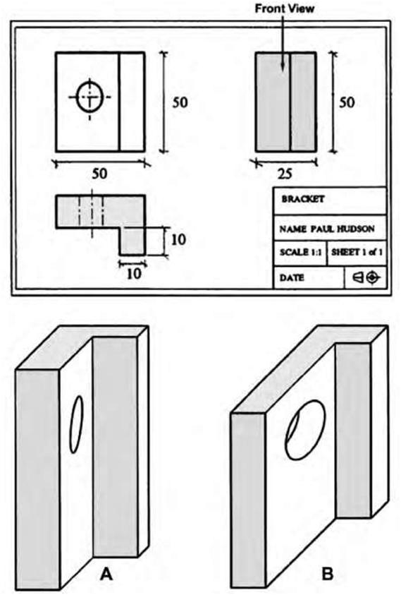
| Figure 5.13A,B A. Oblique drawing with foreshortening. B. Oblique drawing with no foreshortening. Notice how the circle looks elongated (source: Paul Hudson). | |||
| 88 | Chapter 5 | ||
|
thographic projection views. The resulting view then reflects the true shape of the oblique feature while eliminating much time-consuming projection for the drafter. Auxiliary views may be full or partial views. Rounded surfaces and circular holes, which are distorted in the regular views and appear as ellipses, appear in their true sizes and shapes in an auxiliary view, as can be seen in Figure 5.14B. Auxiliary views are named according to the position from which the inclined face is seen. For example, the auxiliary view may be a front, top, bottom, left, or right view (Figure 5.15). In drawings of complex parts involving compound angles, one auxiliary view may be developed from another auxiliary view. The first auxiliary view is called the primary view, and the views developed from it are called secondary auxiliary views. 5.6 AXONOMETRIC PROJECTION |
|||
|
Axonometric projection is a technique used in orthographic pictorials. Within orthographic projection, ax-onometric projection shows an image of an object as viewed from a skew direction in order to reveal more than one side in the same picture, unlike other orthographic projections, which show multiple views of the same object along different axes. Because with axonometric projections the scale of distant features is the same as for near features, such pictures will look distorted, especially if the object is mostly composed of rectangular features. The technique, however, is well suited for illustration purposes. |
|||
 |
|||
| Figure 5.14A,B Two examples of auxiliary-view projections. The illustrations show that the auxiliary views are not one of the primary views of the orthographic projection. | |||
| Types of Views | 89 | ||
 |
|||
| Figure 5.15 Another example of an auxiliary-view projection showing how it relates to an orthographic projection. | |||
|
The distinguishing feature between projections and drawings is the unit of measurement employed. In projections a scale is constructed, which is used for measurements takeoff. The units of measurement used however are variable depending on the projection, and standard units of measurement are not used; in drawings, however, standard units of measurement (e.g. inches, feet, centimeter, etc.) are always used. The scales constructed for isometric, dimetric, and trimetric projections are always smaller than the standard units of measurements from which they are derived. This basically means that axono-metric projections are always smaller than axonometric drawings. An axonometric drawing of an object, although slightly distorted, is nevertheless visually as satisfactory as an axonometric projection of it. Axonometric drawings are usually preferred to axonometric projections because no time is wasted constructing the scales needed to generate the axonometric drawings. An axonometric drawing is one that is accurately scaled and depicts an object that has been rotated on its axes and inclined from a regular parallel position to give it a three-dimensional appearance. The |
|||
| 90 | Chapter 5 | ||
|
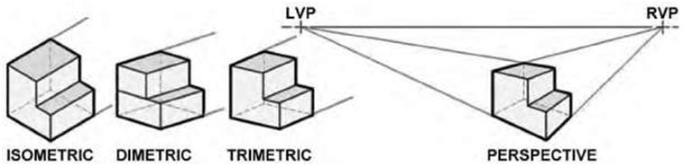
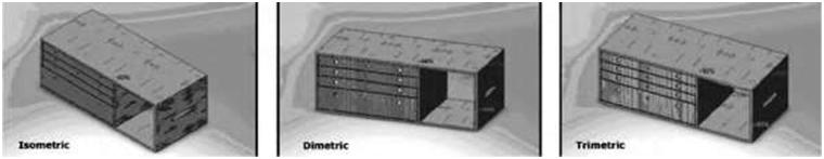
principal advantage of axonometric drawing is that one can use an existing orthographic plan without any redrawing. The plan is simply tilted to the desired angle. It should be noted that in much of Europe, an axonometric drawing always has its axis at a 45-degree angle; an isometric axis is either 30/30 degrees or 30/60 degrees. The most common axonometric drawings are isometric, dimetric, and trimetric (Figure 5.16). Typically in axonometric drawing, one axis of space is shown as the vertical. Axonometric, or planometric, drawing, as it is sometimes called, is a method of drawing a plan view with a third dimension. It is used by interior designers, architects, and landscape gardeners. A plan view is drawn at a 45-degree angle, with the depth added vertically. All lengths are drawn at their true lengths, unlike oblique drawing. This gives the impression that you are viewing the objects from above. One advantage of axonometric drawing is that circles drawn on the top faces of objects can be drawn normally. Isometric Drawing and Isometric Projection The term “isometric” is derived from the Greek for “equal measure,” reflecting that the scale along each axis of the projection is the same, which is not true of some other forms of graphical projection. One of the advantages of isometric perspective in engineering drawings is that 60-degree angles are easy to construct using only a compass and straightedge. The isometric drawing is most commonly used in its true form giving “equal measure” and foreshortened views of three sides of the object. An isometric drawing is one form of pictorial drawing. Hidden lines are not normally inserted. Isometric drawing is a method of visually representing three-dimensional objects in two dimensions, in which the three coordinate axes appear equally foreshortened and the angles between any two of them are 120 degrees. Isometric projection, like orthographic projection. is used in engineering drawings. An isometric drawing can be easily constructed by using a 30-60-90-degree triangle and T-square or with CAD programming. Figure 5.17A and B shows two examples of isometric drawings in an architectural context. Figure 5.17C gives an example of an architectural drawing using both orthographic projection (elevation) and isometric projection (details). |
|||
 |
|||
| Figure 5.16 Different types of axonometric projections (isometric, dimetric, and trimetric) and perspective. In much of Europe, an axonometric uses a 45-degree angle as opposed to the 30/60-degree angles used in isometric drawing. | |||
| Types of Views | 91 | ||
 |
|||
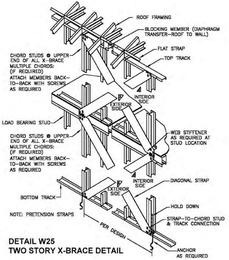
| Figure 5.17A An example of the use of isometric drawings in architecture and engineering (source: North American Steel Framing Alliance). | |||
| 92 | Chapter 5 | ||
 |
|||
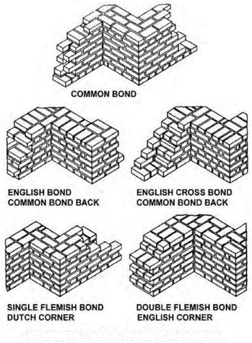
| COMMON TYPES OF BRICK BONDS Figure 5.17B An example of the use of isometric drawings in architecture and engineering. |
|||
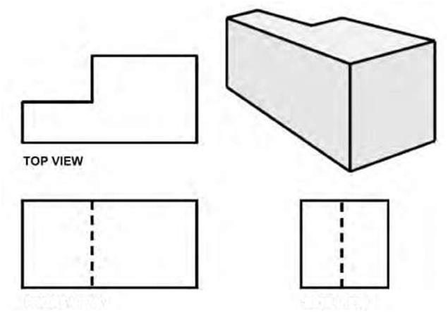
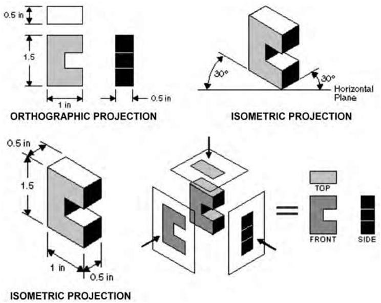
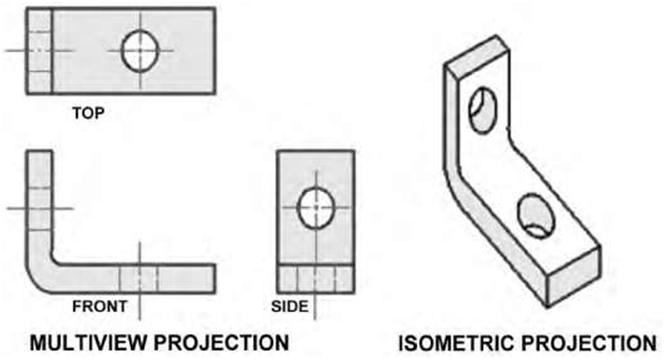
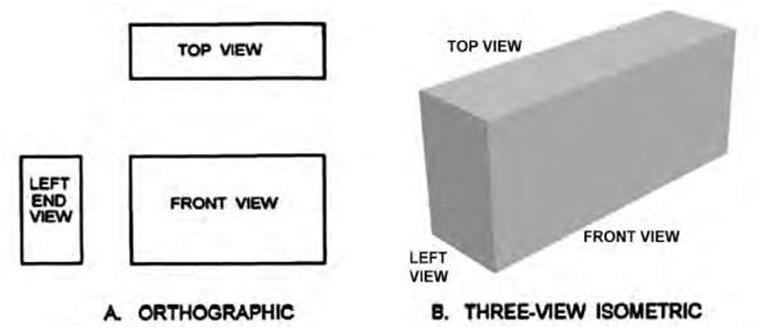
| Comparison of Isometric and Orthographic Drawings Compare the simple rectangular block shown in the orthographic representation (third-angle projection) in Figure 5.18 and the three-dimensional isometric representation. Notice that the vertical lines of the orthographic and isometric drawings (views A and B) remain vertical. The horizontal lines of the orthographic drawing are not horizontal in the isometric drawing but are projected at 30- and 60-degree angles; the length of the lines remains the same in the isometric and in the orthographic drawings. |
|||
| Types of Views | 93 | ||
 |
|||
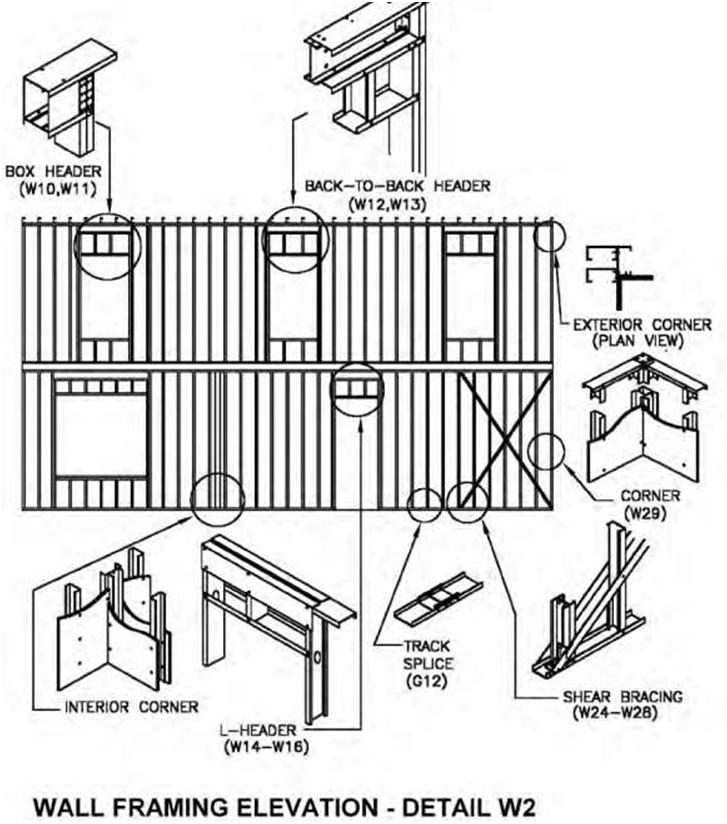
| Figure 5.17C An example of the use of isometric drawings in architecture and engineering (source: North American Steel Framing Alliance). | |||
| 94 | Chapter 5 | ||
| Purpose of Isometric Drawing The task of an isometric drawing is primarily to show a three-dimensional picture in one drawing. It is like a picture that lacks artistic details. Many utilities workers have difficulty in clearly visualizing a piping or ducting installation when they are working from a floor plan and an elevation drawing. The isometric drawing facilitates understanding by combining the floor plan and the elevation. It clearly communicates the details and clarifies the relationship of the pipes in an installation. Although isometric drawings are not normally drawn to scale on blueprints, some architects and engineers prefer drawing them to scale. Isometric drawings, like other types of drawings, follow certain rules and conventions to show three dimensions on a flat surface. Dimensioning Isometric Drawings An isometric drawing, or sketch, is dimensioned with extension and dimension lines in a manner somewhat similar to that of a two-dimensional drawing. The extension lines extend from the drawing, and the dimension lines are parallel to the object line and of equal length to it. Dimensioning the isometric drawing is more difficult because it consists of a single view, with less room available than on three separate views. Circles or holes will be skewed or drawn within an isometric square. For example, a circle will appear elliptical in shape and is actually drawn by connecting a series of four arcs, drawn from the center-lines of the isometric square. The ellipses may also be drawn with the use of templates. Curved or round |
|||
 |
|||
| Figure 5.18 A. Orthographic views of an object (third-angle projection). B. Three-view isometric drawings of the same object. | |||
| Types of Views | 95 | ||
|
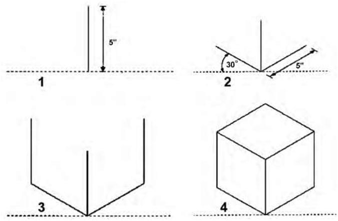
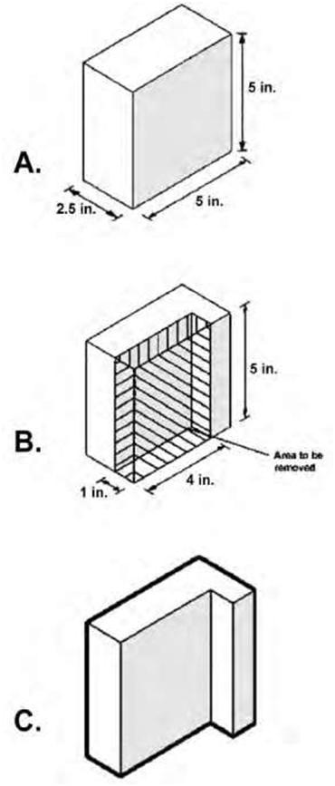
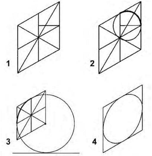
corners are drawn in the same manner by locating the end of the radius on the straight line and then connecting the two points to form a triangle. The third point of the arc is actually the center of the triangle. Connect the three points with a freehand arc. In isometric projections the direction of viewing is such that the three axes of space appear equally foreshortened. The displayed angles and the scale of foreshortening are universally known. However, in creating a final, isometric instrument drawing, a full-size scale—i.e., without the use of a foreshortening factor—is often employed to good effect because the resultant distortion is difficult to perceive. Isometric drawing render a three-dimensional view of an object in which the two sets of horizontal lines are drawn at equal angles and all vertical lines are drawn vertically. In the resulting drawing all three angles are equally divided about a center point, and all three visible surfaces have equal emphasis. Orthographic techniques cannot be used in isometric drawings. Any angle can be used to draw an isometric view, but the most common is 30 degrees because it can be drawn with a standard triangle and gives a fairly realistic view of an object. Today, CAD programs are the easiest way to draw isometric projections, but isometrics are also quick to draw manually and can be measured at any convenient scale. To manually draw in isometric, you will need a 30/60-degree set square. There are four simple steps to manually draw a 5-inch box in isometric (Figure 5.19): 1. Draw the front vertical edge of the cube. 2. The sides of the box are drawn at 30 degrees to the horizontal to the required length. 3. Draw in the back verticals. 4. Drawn in top view with all lines drawn 30 degrees to the horizontal. When you first start working with isometric techniques, use a simple box as a basic building block or guide to help you draw more complicated shapes. Figure 5.20 shows how to use such a simple box to accurately draw a more complicated L shape. The first step is to lightly draw a guide box. This box is the size of the maximum dimensions. In this case, it measures 5 inches in length, 2.5 inch in width, and 5 inches in height. To achieve the L shape, we need to remove an area from this box. Draw a second box measuring 4 x 1 x 5 inches, the shape that needs to be removed from the first box to create the shape we require. For the finished shape, draw in the outline of the object using a heavier line. By using this technique complex shapes can be accurately drawn. Circles in isometric do not appear circular. They appear skewed and are actually elliptical. There are several methods of constructing circles in isometric drawing. For many manual tasks the easiest method is to use an isometric circle template, which can be bought at most good art shops. These templates contain a number of isometric circles of various sizes. Isometric circles can also be drawn manually using the following method: 1. Draw an isometric square and then draw in the diagonals, a vertical, and a line at 30 degrees from the midpoint of the sides, as illustrated in Figure 5.21. 2. Place your compass point on the intersection of the horizontal and the vertical lines and draw in a circle that touches the edges of the box 3. For the next section of the isometric circle place your compass point on the corner of the isometric square and draw in the arc as shown in the illustration. 4. Complete the circle by repeating the process for the other parts, using the appropriate techniques. |
|||
| 96 | Chapter 5 | ||
 |
|||
| Figure 5.19 The four steps in drawing a simple 5-inch box in isometric. Note that all lengths are actual size in standard isometric drawings. | |||
| Dimetric Projection Dimetric projection is an axonometric projection of an object placed in such a way that two of its axes make equal angles with the plane of projection and the third axis makes either a smaller or a greater angle. In dimetric projections, the directions of viewing are such that two of the three axes of space appear equally foreshortened, with the attendant scale and angles of presentation determined according to the angle of viewing; the scale of the third direction (vertical) is determined separately. Approximations are common in dimetric drawings. Figure 5.22 shows different arrangements for isometric, dimetric, and tri-metric drawings. |
|||
| Trimetric Projection Trimetric projection is an axonometric projection of an object so placed that no two axes make equal angles with the plane of projection and each of the three principal axes and the lines parallel to them, re- |
|||
| Types of Views | 97 | ||
 |
|||
| Figure 5.20 Steps to draw a circle in isometric projection. | |||
| 98 | Chapter 5 | ||
 |
|||
| Figure 5.21 Steps to draw a circle in isometric projection. | |||
 |
|||
| Figure 5.22 A comparison of isometric, dimetric and trimetric drawings (source: Wikipedia). | |||
| Types of Views | 99 | ||
|
spectively, have different ratios of foreshortening (and are therefore drawn at different scales) when projected to the plane of projection. The wide angle choice gives the designer considerable flexibility and control of the pictorial view. In trimetric projections, the direction of viewing is such that all of the three axes of space appear unequally foreshortened. The scale along each of the three axes and the angles among them are determined separately as dictated by the angle of viewing. Approximations in trimetric drawings are common. Limitations of Axonometric Projection Objects drawn with axonometric projection do not appear larger or smaller as they extend closer to or further away from the viewer. While advantageous for architectural drawings and sprite-based video games, this results in a perceived distortion, as, unlike perspective projection, it is not how our eyes or photography usually work. An additional problem in the case of isometric projection is that there are times when it becomes difficult to determine which face of the object is being observed. In the absence of proper shading, and with objects that are relatively perpendicular and similarly proportioned, it can become difficult to determine which is the top, bottom, or side of the object, since each face is given similar dimensions. |
|||
| 5.7 PICTORIAL DRAWINGS | |||
|
Pictorial drawings are not often used for construction purposes. However, on some working drawings pictorial views are used to reveal information that orthographic views alone would be incapable of showing; other situations may require a pictorial drawing essentially to supplement a major view. Pictorial projection, unlike multiview projection, is designed to allow the viewer to see all three primary dimensions of the object in the projection. Pictorial architectural drawings and renderings are very easy to understand and are therefore used extensively to depict a three-dimensional view of an object and for explaining project designs to laypersons for sales-presentation purposes. They enable an inexperienced person to interpret drawings and quickly visualize the shape of individual parts or various components in complicated mechanisms. To convey as much information as possible, the view is oriented to show the sides with the most features. In many cases, orthographic (multiview) drawings provide information in a format that makes it difficult for laypersons to visualize the total project. Orthographic/multiview drawings are typically dimensioned and are usually drawn to a specific scale (Figure 5.23). Although pictorial drawings may be dimensioned and drawn to scale, their main purpose is to give a three-dimensional representation of the building or object. As illustrators often take artistic liberties with scale and proportion, the reader should only use pictorial drawings for general reference. And although they are not usually dimensioned and exact scaling is not required, proportions are nevertheless expected to be maintained. When pictorial drawings are dimensioned and contain other specifications that are needed to produce the part or construct the object, they are considered to be working drawings. Whereas a multiview drawing is designed to focus on only two of the three dimensions of the object, a pictorial drawing provides an overall view. The tradeoff is that a multiview drawing generally allows a less distorted view of the features in the two dimensions displayed while lacking a holistic view of the object (thus needing multiple views to fully describe the object). |
|||
| 100 | Chapter 5 | ||
 |
|||
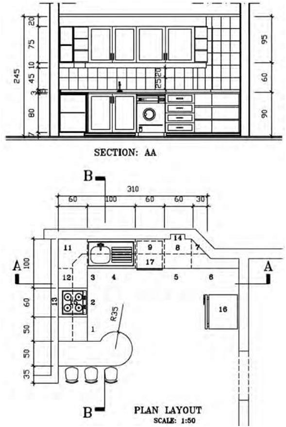
| Figure 5.23 Drawing showing an orthographic view (plan and section) of a kitchen design. | |||
| Types of Views | 101 | ||
| The same dimensioning rules that apply for an orthographic/multiview drawing also apply to a pictorial drawing. These include: Dimension and extension lines should be drawn parallel to the pictorial planes. When possible, dimensions are placed on visible features. Arrowheads lie in the same plane as extension and dimension lines. Notes and dimensions should be lettered parallel to the horizontal plane. The three main types of pictorial drawings that are extensively used in architectural presentations are perspective drawings, isometric drawings, and oblique drawings. The main difference between isometric and typical perspective drawings is that in the latter the lines recede to vanishing points. This gives the drawing a more realistic appearance but is technically inaccurate. Isometric drawings, on the other hand, show true dimensions. However, they create an optical illusion of distortion, mainly because the human eye is accustomed to seeing long object lines recede. For this reason, isometric drawings are primarily utilized for clarification of small construction details, since they depict their true size dimensions. In an oblique drawing two or more surfaces are shown at one time on one drawing. The front face of an object is drawn in the same way as the front view of an orthographic sketch. 5.8 PERSPECTIVE DRAWINGS |
|||
|
A good understanding of the principles of perspective is necessary to create an accurate and visually appealing piece of art. Perspective drawings are forms of pictorial drawing. Blueprint readers may not see a perspective drawing very often, but they will undoubtedly appreciate the descriptive information it offers. Perspective drawing is a system for representing three-dimensional space on a flat surface. It utilizes either one, two, or three points to where the receding lines will vanish. These vanishing points are placed along a horizontal line called a horizon line. In perspective drawings receding lines are no longer parallel to each other as in oblique or isometric drawings. In perspective drawings, distant objects appear smaller but have the same shape and proportions as they would close up. In other words, as objects are further away, they become smaller and appear to vanish into the distance. The general principle behind perspective drawing is simple and shares many features with the way people actually perceive space and objects in it. It depends essentially on four interconnected criteria that will invariably affect the final image: the level of our eyes when viewing the scene or object, thus determining the horizon line; the distance from the picture plane to the object; the distance from the station point to the object and cone of vision; and the angle of the object to the picture plane. Perspective drawings may be drawn as impressive artistic renderings to show landscapes or large structures. They can also be used to show a realistic representation of machine parts or layouts of architectural furnishings in a room. Perspective drawings are more difficult and time-consuming and are not used as extensively as they might be. They are used mainly for illustrative purposes, but their use as a descriptive drawing in manufacturing environments should not be overlooked. In essence, there are three basic types of perspective drawings that are commonly used in architectural design and construction: one-point perspective, two-point perspective, and three-point perspective. |
|||
| 102 | Chapter 5 | ||
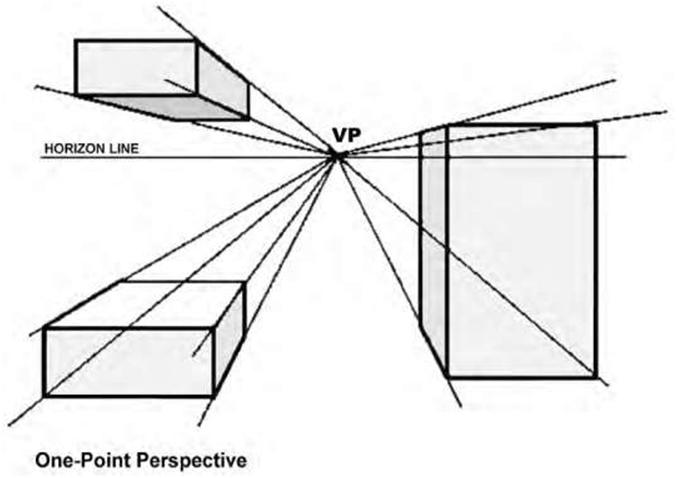
| One-Point (Parallel) Perspective The law of perspective is that parallel lines that lie in the same plane will appear to converge to a single point somewhere on the horizon (at the eye level), called the vanishing point (VP). This point is usually positioned within the view and gives objects an impression of depth. To draw a one-point perspective, simply draw a horizon line (HL) and draw a vanishing point anywhere on it. The horizon line may be located above, below, or at any other location on the drawing. Vertical and horizontal lines are drawn normally, and all receding lines are drawn to the vanishing point. Thus, the sides of an object diminish towards the vanishing point, whereas all vertical and horizontal lines are drawn with no perspective—i.e., face on (Figure 5.24). A normal-view angle places the HL at a natural height as if the viewer were looking straight ahead without tilting the head up or down. Figure 5.25 shows two examples of normal-view one-point perspective. Altering the position of the VP changes the view of the object being drawn. For example, to look down at the top of the object, the vanishing point must be above the horizon line while to look up at the object, it must be below the horizon line. It is advisable to practice identifying the best locations for vanishing points to achieve the desired results. One-point perspective depicts a building or interior space with one side parallel to the picture plane (perpendicular to the observer’s line of sight). To set up a one-point perspective, connect the corners of the elevation to the vanishing point and mark off the depth through the lines of sight in the plan (Figure 5.26). One-point perspectives are often used to draw interiors, as they give an accurate depiction of the facing wall, in addition to both receding side walls. They are also typically used for roads, railroad tracks, interiors, and buildings viewed so that the front is directly facing the viewer. Objects that are made up of lines either directly parallel or perpendicular to the viewer’s line of sight can be drawn with one-point perspective. However, it is of limited use, mainly because the perspective is too pronounced for small products, making them appear larger than they actually are. Two-Point Perspective Sometimes called angular perspective drawing; in this method only the vertical lines are drawn vertically. The horizontal, depth, and length receding lines are drawn to the vanishing points located on the horizon line. The front view is no longer true in shape but is now drawn in an isometric configuration. Again, the location of the horizon line and the vanishing points on the line will provide many different “looks” of the object. In two-point perspective the sides of the object vanish to one of two vanishing points on the horizon. Vertical lines in the object have no perspective applied. Our distance from an object seen at an angle determines where the vanishing points lie on the horizon. Two-point perspective is a much more useful drawing system than the simpler one-point perspective and the more complex three-point perspective. Objects drawn in two-point perspective have a more natural look. Figure 5.27 illustrates a typical architectural application of two-point perspective for a department-store interior. To set up a two-point perspective, connect the corner height line to the right and left vanishing points, and, with the lines of sight in the plan, mark off the depth of the object. The procedure for constructing a two-point perspective view is essentially the same as for one-point perspective except for the additional step of establishing two vanishing points. In two-point perspective you can make the object look big or small by altering the proximity of the vanishing points to the object (Figure 5.28). Shade and shadow are often used in perspective drawings to give a better perception of the depth and form of a space or object. The drawing of shadows and reflections both follow the same immutable rules of perspective. |
|||
| Types of Views | 103 | ||
 |
|||
| Figure 5.24 A simple one-point perspective. Although it is possible to sketch products in one-point perspective, the perspective is often too aggressive to the eye, making objects appear bigger than they actually | |||
| are. | |||
| The illustration in Figure 5.29 demonstrates how to draw a box in two-point perspective: 1. Put two vanishing points at opposite ends of the horizontal line. 2. Draw the front vertical of the box. Drawing the line below the horizontal will create a view that we are looking down on. To look at the object from below, draw the front vertical above the horizontal. 3. Draw lines from the top of the vertical that disappear to both of the vanishing points. Repeat the process for the bottom of the line. 4. To complete both sides, draw in the back verticals. 5. To draw the top of the box, draw lines from the back verticals to the opposite vanishing points. |
|||
| 104 | Chapter 5 | ||
 |
|||
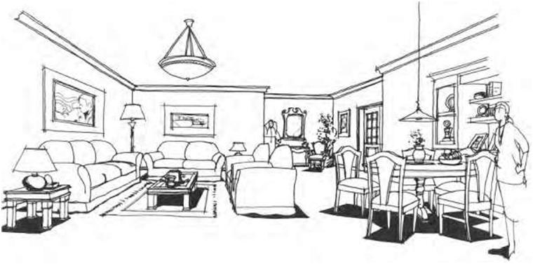
| Figure 5.25A A. Illustration of an interior using normal-view one-point perspective. | |||
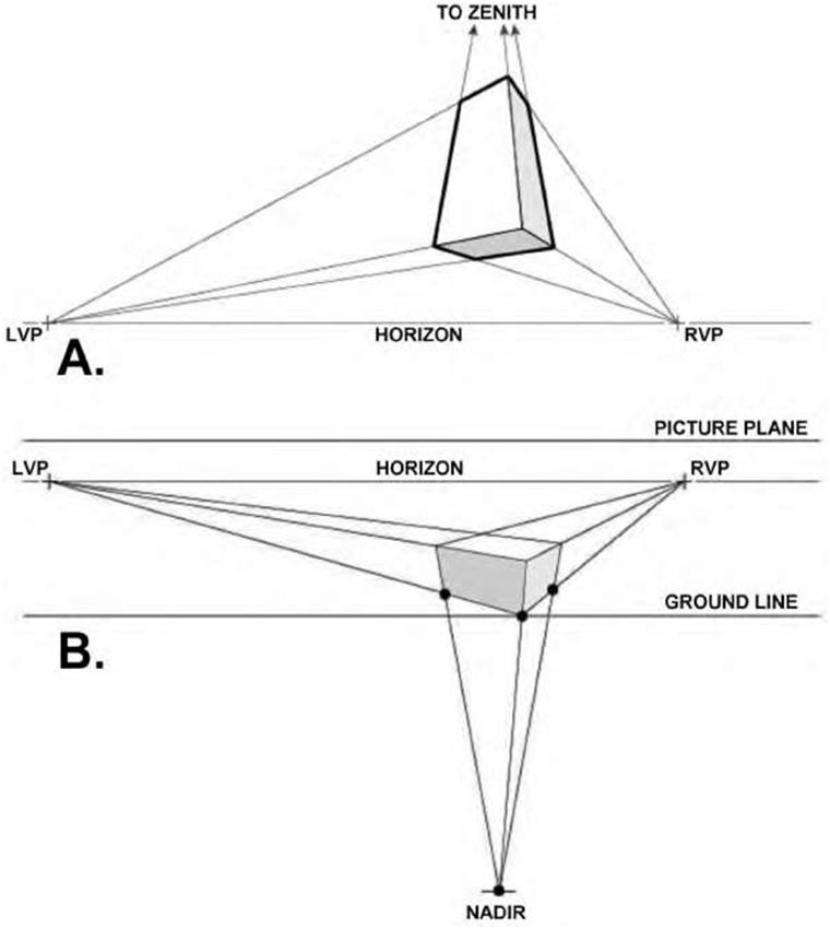
| Three-Point Perspective Three-point perspective is a development of two-point perspective and is usually used for buildings seen from above or below. Like two-point perspective it has two vanishing points somewhere on the horizon and a third somewhere above or below the horizon line toward which the verticals converge (Figure 5.30). This means that the object is either tilted to the picture plane or the spectator’s central axis of vision is inclined upward or downward and the picture plane is tilted. Three-point perspectives usually indicate that the spectator is very close to the object or that the object is very large. It is best used for drawing tall objects such as buildings, although this form of perspective is not widely used in architectural presentations. Its best use may be to show a particular viewpoint of a tall object such as a skyscraper. This type of drawing is sometimes called an oblique perspective drawing, as the vertical lines are drawn to the third vanishing point not located on the horizon line. Four-, five-, and six-point perspective drawings are more complex and challenging and require considerable understanding and skill to execute. In general, most designers create drawings with a vanishing point far below the horizon so that the depth added to the verticals is only slight. In many cases the vanishing point isn’t even on the paper. Learning how to apply vertical perspective will make your drawings more and more realistic. |
|||
| Types of Views | 105 | ||
 |
|||
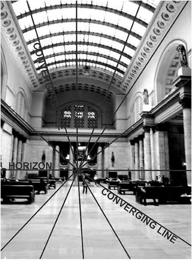
| Figure 5.25B A photograph of an interior space depicting a normal-view one-point perspective and showing the converging lines and horizon (source: Randy Sarafan). | |||
| 106 | Chapter 5 | ||
 |
|||
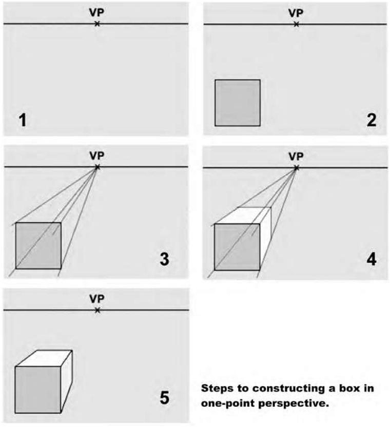
| Figure 5.26 To construct a box in one-point perspective, draw a horizon line (HL) and place a vanishing point (VP) somewhere on this line; draw a square somewhere beneath the horizon—this will be the front of your box; draw four lines, one from each corner of the square that must pass through the vanishing point; and lastly, draw in the back vertical and horizontal to complete the box. | |||
| Types of Views | 107 | ||
 |
|||
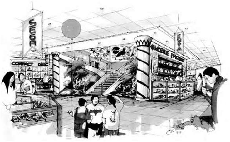
| Figure 5.27 A typical architectural application of a two-point perspective used to show a department store interior. | |||
 |
|||
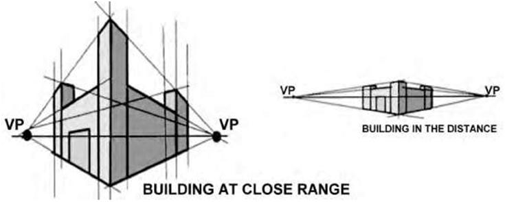
| Figure 5.28 In two-point perspective you can make the object look big or small by altering the proximity of the vanishing points. In the image on the left the vanishing points are close to the building; the image on the right shows the vanishing points far away from the building. | |||
| 108 | Chapter 5 | ||
 |
|||
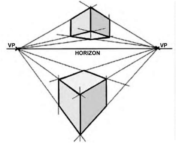
| Figure 5.29 A simple two-point perspective of objects drawn above and below the horizon line. | |||
| Types of Views | 109 | ||
 |
|||
| Figure 5.30A,B Two examples of a three-point perspective, one with the vanishing point above the horizon and the other with it below (source: Kevin Hulsey). | |||