
| 2.1 INTRODUCTION | |||
|
Not too long ago, it was predicted by some that by the beginning of the 21st century, blueprints would become obsolete and no longer be used on construction sites. It was further suggested that construction information would essentially be read off computer screens rather than blueprint drawings. This would not only be more efficient, but it would also save a tremendous amount of paper. These predictions did not materialize. Although construction plans are read regularly on computer screens and are being sent via computer to job sites, paper blueprint drawings remain the preferred medium on building sites. In many parts of the world, manual drafting and blueprint drawings are still the norm. Blueprint reading consists essentially of finding information on prints. The information may be displayed on a drawing in the form of lines, notes, symbols, and schedules. The items are typically located either in the title block or in the field of the drawing (i.e., anywhere within the border lines outside the title block). You should also keep in mind that blueprints typically come in sets. A set of prints for a single-family residence may contain no more than a few sheets, whereas on a large project a complete drawing set may contain scores of sheets for different disciplines (e.g., architectural, structural, electrical, mechanical, plumbing, etc.). The general process and sequence for reading blueprints can be summarized as follows: 1. Verify that the set of drawings and specifications is complete. Likewise, verify that the documents in hand are the most current. 2. Start by reviewing the site or plot plan to better comprehend the setting of the building and the general topography. |
|||
| Copyright © 2009 by The McGraw-Hill Companies, Inc. Click here for terms of use. | 9 | ||
| 10 Chapter 2 | ||
|
3. Visually scan the architectural drawings to get a better overall understanding of the project. Look at the title block to extract any general information pertaining to the project that may be needed (consultant’s name, client’s name, project title, drawing number, etc.). Check for unusual or complicated features that may impact how the building is constructed. In particular review the elevations and sections and the materials used. 4. Review the foundation plan and read the general notes to get a better understanding of the construction specifications and other information relevant to the drawing. Also look at the relevant building details. 5. Review the structure’s wall construction and the material and methods used. Also study the details showing how the wall is to sit on the designed foundations and which walls if any are load-bearing and which are not. 6. Review the plumbing, mechanical, and electrical drawings. 7. Check all notes on these plans to see if there have been any revisions. Check to see if the building codes have been taken into account. Ensure that the notes on the drawings are clear and that there is no ambiguity. 8. Review the specifications and compare them to the drawings. (Specifications normally have priority over drawings.) If there are discrepancies, the consultant should be notified. 2.2 TECHNICAL DRAWING |
||
|
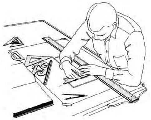
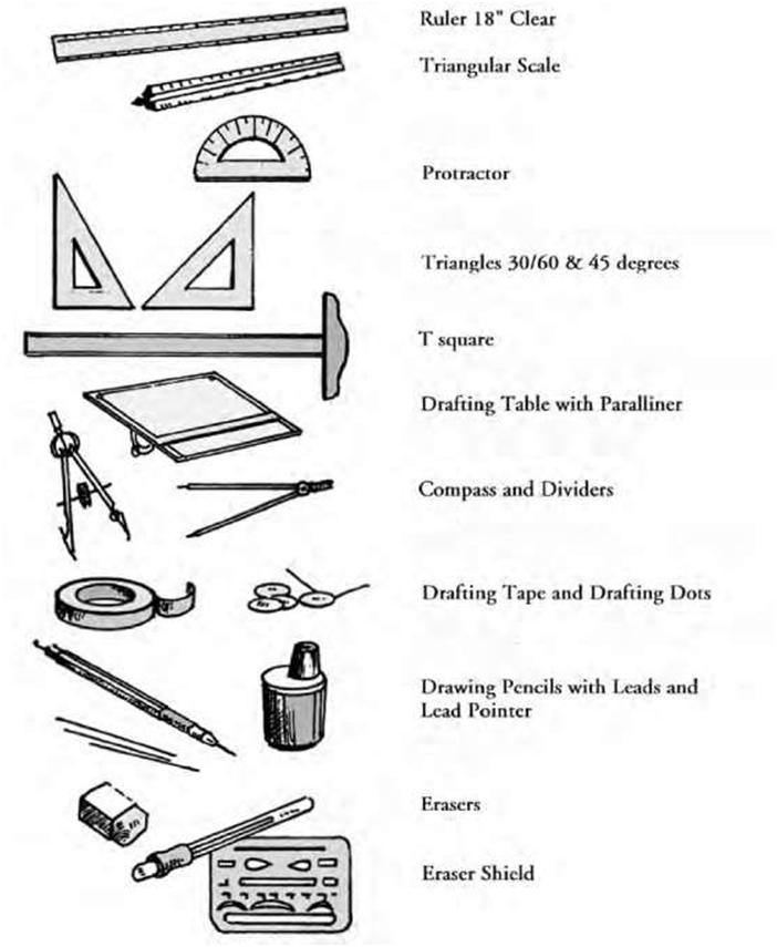
Also known as drafting, technical drawing is the practice of creating accurate representations of objects for architectural and engineering needs. A practitioner of the discipline is known as a drafter. Today the mechanics of the drafting task have considerably changed through the use of CADD computer systems, but regardless of whether a drawing is drawn manually or with computer assistance, it must be reproducible. Manual Drafting Basic drafting procedure consists of placing a piece of paper (or other material) on a smooth surface with right-angle corners and straight sides–typically a drafting table. A sliding straightedge commonly known as a t-square is then placed on one of the sides, allowing it to slide across the side of the table and over the surface of the paper (Figure 2.1). Parallel lines can be drawn by simply moving the t-square and running a pencil or technical pen along the edge. The t-square is also used as a means to hold other tools such as set squares or triangles. To do this, the drafter places one or more triangles of known angles on the t-square (which is itself at right angles to the edge of the table) and then draws lines to the angles chosen on the sheet. Modern drafting tables (which in the United States are rapidly being replaced by CAD stations) come equipped with a parallel rule that is supported on both sides of the table to slide over the tracing paper. Since it is secured on both sides of the drafting table, lines drawn along the edge are parallel. The drafter also has other tools at his/her disposal that are used to draw curves and circles, including compasses (used for drawing simple arcs and circles) and French curves (which typically consist of a piece of plastic with complex curves on it). Another tool used is the spline, which is a piece of rubber-coated articulated metal that can be manually bent to most curves. Figure 2.2 is an illustration of some of the templates and instruments used in manual drafting. |
||
| Blueprints and Construction Drawings: A Universal Language | 11 | ||
|
Drafting templates allow the drafter to consistently recreate recurring objects in a drawing without continuously having to reproduce them from scratch. This is particularly useful when using common symbols: for example, in the context of stagecraft, a lighting designer will typically draw from the United States Institute for Theatre Technology (USITT) standard library of lighting-fixture symbols to indicate the position of a common fixture across multiple positions. Templates can usually be purchased from various vendors, usually customized to a specific task, but it is also not uncommon for a drafter or designer to create customized templates. This basic drafting system requires an accurate table, and careful attention should be given to the positioning of the tools. A common error is to allow the triangles to push the top of the t-square down slightly, thereby throwing off all the angles. Even tasks as simple as drawing two angled lines meeting at a point require a number of moves of the t-square and triangles. In general, drafting often proves to be a time-consuming process. A solution to these problems was the introduction of the so-called mechanical drafting machine, an application of the pantograph that allowed the drafter to make an accurate right angle at any point on the page quite quickly. These machines often included the ability to change the angle, thereby removing the need for the use of triangles as well. In addition to the complete mastery of the mechanics of drawing lines, circles, and text onto paper (with respect to the detailing of physical objects), the drafting effort requires a proficient understanding of geometry, trigonometry, spatial comprehension, and above all a high standard of precision and accuracy as well as close attention to detail. |
|||
 |
|||
| Figure 2.1 A drafter using a typical drawing board, t-square, and other instruments (after Muller, Edward J., et al.: Architectural Drawing and Light Construction, 5th ed., Englewood Cliffs: Prentice Hall, 1999). | |||
| 12 | Chapter 2 | ||
 |
|||
| Figure 2.2 Some of the tools, aids and materials used in manual drafting (from Montague, John: Basic Perspective Drawing: A Visual Approach, 3rd ed., New York: John Wiley and Sons, 1998). | |||
| Blueprints and Construction Drawings: A Universal Language | 13 | ||
| Lettering Lettering is used on construction drawings as a means to provide written information. A construction sketch or drawing without lettering rarely communicates an adequate description of the object. It is almost always necessary to provide additional labels, notes, and dimensions to clarify the size, type of materials, and location of the component. Drawings are therefore a means of communication of information to others, and text generally is one of the main mediums to transmit information in the form of notes, titles, dimensions, etc. Lettering should enhance a drawing by making it easy to interpret and pleasant to look at; it should not detract from the drawing or be illegible or unsightly to look at. Legibility and consistency are the key ingredients to good lettering. Architectural lettering is often done using all uppercase letters, and abbreviations are commonly used to save space and drafting time (refer to the abbreviation list in the Appendix). When necessary, specific notes can be placed close to the item being identified or connected to it with leader lines. Although most of the lettering done today on construction drawings is computer-generated, skill in freehand lettering adds style and individuality to a designer’s work. And in any style of lettering, uniformity is important. This applies to height, proportion, strength of lines, spacing of letters, and spacing of words. Letters should be spaced by visually equalizing the background areas between the letterforms and not by mechanically measuring the distance between the extremities of each letter (Figure 2.3). The use of light horizontal guidelines (using a hard lead such as a 4H) should be practiced to control the height of letters, while light vertical or inclined guidelines are required to keep the letters uniform. Words should be spaced well apart, while letters should be spaced closely within words. A cursory examination of the various alphabets and typefaces in use today clearly shows that the vast majority fit into one of four basic classifications as outlined below (Figure 2.4): Roman: perfected by the Greeks and Romans and later modernized in the 18th century, the Roman alphabet displays enormous grace and dignity and is considered by many to be the most elegant typeface family. Gothic: this alphabet is the base from which our single-stroke technical lettering has evolved and is the primary style used by the majority of today’s designers. It is an easily read and simply executed style that has been in use for many years as a commercial, block-type letter. Its main characteristic is the uniformity in width of all of the strokes. Modifications of this letter include inclined, squared, rounded, boldface, lightface, and serif. Script: script alphabets are cursive in nature and resemble handwriting. The lowercase letters are interconnected when used within words or sentence beginnings. Their characteristic free-flowing strokes impart a sense of delicacy and personal temperament and are not considered appropriate for general use in technical drawing. Text (Old English): originally used by European monks for recording religious manuscripts, this alphabet is characterized by the use of strokes of different width, due to the original employment of a flat quill pen. This alphabet is rarely used in modern work and is not considered suitable for technical drawing because it is difficult to read and draw. All of the above typefaces can be produced in italic (which has inclined, lightface, and curved characteristics). The character of the typeface used should always be appropriate to the design being presented. Today there is a large body of well-designed typefaces available in the form of pressure-sensitive dry-transfer sheets in addition to computerized typography. |
|||
| 14 | Chapter 2 | |||
| T¥pog^ap/iY abcdef$h/ji:!nnopqr5>tuvwxyz abcdefghijklmnopqrstuvwxyz 0123456789 AieDEFiHUK hi i p q v 11 m w 11 f; |
||||
| i^^©DK]i | M tS | |||
| Correct spacing of equal areas | Incorrect spacing of letter forms | |||
| SERIFS Serifs | ||||
| Figure 2.3 Examples of some of the more popular typefaces used today. | ||||
| ROMAN GOTHIC | ||||
| Figure 2.4 Most alphabets currently in use can be classified into four basic categories: Roman, gothic, script and text. | ||||
| Blueprints and Construction Drawings: A Universal Language 15 2.3 COMPUTER-AIDED DRAFTING (CAD) AND COMPUTER-AIDED DESIGN AND DRAFTING (CADD) |
||
|
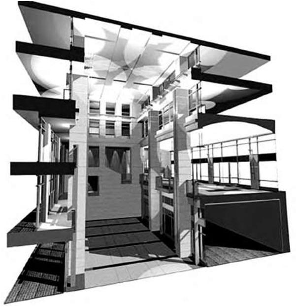
Moving from manual drafting to computer-aided design and drafting was an important step in terms of the potential of today’s technology. CAD originally meant computer-aided drafting because of its original use as a replacement for traditional drafting. Now it usually refers to computer-aided design to reflect the fact that modern CAD tools do more than just drafting (Figures 2.5A, B, and C). Related acronyms are CADD, which stands for computer-aided design and drafting; CAID, for computer-aided industrial design; and CAAD, for computer-aided architectural design. All of these terms are essentially synonymous, but there are a few subtle differences in meaning and application. CAM (computer-aided manufacturing) is also often used in a similar way or as a combination (CAD/CAM). When we use computer-aided design and drafting (CADD), certain questions arise that we never think of when working on the drawing board. Although with CAD or CADD we do not use the typical drawing-board tools, we are still required to design or make a drawing. CADD is an electronic tool that enables you to rapidly create accurate drawings with the use of a computer. In fact, an experienced computer drafter can normally produce a construction drawing in less time than it would take if it was done manually. Moreover, unlike the traditional methods of making drawings on a drawing board, with CADD systems you can create professional drawings just by using a mouse and clicking buttons on the keyboard. Furthermore, drawings created with CADD have many advantages over traditionally produced drawings. In addition to the fact that they are neat, accurate, and highly presentable, they can be easily modified and converted to a variety of formats. In addition, CADD-generated drawings can be saved on the computer, a flash, a CD, or an external hard drive in lieu of vellum or Mylar sheets that require the use of large storage cabinets for filing. A decade ago CADD was largely used for specific engineering applications that required high precision, and because of CADD’s high production costs, not many professionals could afford it. In recent years, however, computer prices have dropped significantly, and professionals are increasingly taking advantage of this by adopting CADD programs. There is a wealth of CADD programs available on the market today. Some are intended for general drawing work, while others are designed for specific engineering applications. There are programs that enable you to do 2D drawings, 3D drawings, renderings, shadings, punch lists, space planning, structural design, piping layouts, HVAC, plant design, project management, and other applications. Today we can find a CADD program for almost every engineering discipline that comes to mind. CADD Presentations Although CADD is primarily intended for single-line drafting and has very limited capabilities to create artistic impressions, CADD’s 3D and rendering features are quite impressive. A 3D model of an object can be created and viewed from various angles and, with correct shading and rendering, can be made to look very realistic. With CADD you can create fine drawings with hundreds of colors, line types, hatch patterns, presentation symbols, text styles, and other features. Even if you don’t like something about your presentation after you have finished it, you can instantly change it (Figure 2.6). Most CADD programs have a number of ready-made presentation symbols and hatch patterns available that can be used to enhance the look of drawings. When drawing a site plan, for example, a draftsperson can instantly add tree symbols, shrubs, pathways, human figures, and other landscape elements to create a professional-looking site plan. Similarly, an architect can use ready-made symbols |
||
| 16 | Chapter 2 | ||
 |
|||
| Scale: 1/4″ = TO’ Figure 2.5A Example of a type of CADD-generated drawing. |
|||
| Blueprints and Construction Drawings: A Universal Language | 17 | ||
 |
|||
| Figure 2.5B Example of a type of CADD-generated drawing. | |||
| of doors, windows, and furniture to make a presentation. Architects and designers also sometimes design their own symbols when working with CADD. In addition to preparing impressive presentations on paper, CADD can be used to make on-screen presentations. Ideas can be presented on-screen by merely plugging the computer to a projector. Advanced CADD programs also allow you to created animated images. You can show how a building would appear while walking through it or how a machine assembly will operate as different machine parts move. |
|||
| Editing Flexibility One of the main advantages of CADD is that it allows quick alterations to drawings. Modifications can be made with pinpoint accuracy. It takes only seconds to do a job that would otherwise take hours on a drawing board to produce. In many cases you may not even have to erase a section to make the change. |
|||
| 18 | Chapter 2 | ||
 |
|||
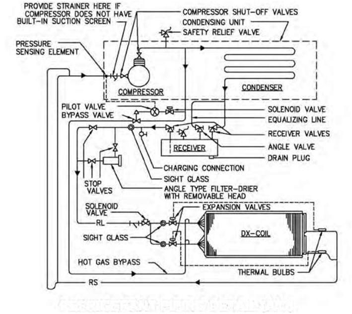
| REFRIGERANT PIPING DETAIL (A/C) Figure 2.5C Example of a type of CADD-generated drawing. |
|||
| You can often rearrange the existing components of the drawing to fit the new shape. This enables the designer to compare various options with minimal effort. The following are some of the main editing capabilities of most CADD systems: Move, copy, mirror, or rotate drawing elements with ease Enlarge or reduce elements of a drawing Make multiple copies of a drawing element Add one or more drawings to another drawing Change font style and size |
|||
| Blueprints and Construction Drawings: A Universal Language | 19 | ||
 |
|||
| Figure 2.6 Example of a presentation perspective using ArchiCAD software. | |||
| Change units of measure of dimensions Stretch drawings to fit new dimensions Convert CADD drawings to other formats Units and Accuracy Levels CADD allows you to work with greater accuracy. If you need to create highly accurate geometrical shapes, while avoiding time-consuming mathematical calculations, CADD is the answer. Computer-software programs like CADD allow the designer to work with different units of measure, such as architec- |
|||
| 20 | Chapter 2 | ||
|
tural units, engineering units, scientific units, and surveyor’s units. These units can be represented in various formats commonly used by professionals. When working with engineering units, the designer or drafter can specify whether all the dimensions should be represented in inches, feet-inches, centimeters, or meters. Angular units of measurement such as decimal degrees, minutes, seconds, or radians can also be chosen. In general, when there is a need to work on a large-scale drawing such as a plan of a township, a high degree of accuracy may not be warranted, and it may be decided to set a lesser degree of accuracy—say ,1 foot, 0 inches. The computer will then round off all the measurements to the next foot, which avoids the use of any fractions less than a foot. Where minute detail is required, a higher degree of accuracy such as 1/8 or 1/64 inch may be set. Drawings Storage and Access As previously mentioned, it is simple, quick, and convenient to generate or organize a CADD drawing on a computer. Most computer hard drives have the capacity to store thousands of drawings (and this storage capacity is continuously increasing with advancing technology), and they can be opened within seconds. Some of the advantages of a computer’s electronic filing system over traditional filing include: It enables and encourages the creation of a highly organized and efficient environment. It contributes to large reductions in general working space. An electronic drawing does not age or become faded. Whenever a new drawing is required, it can be printed from disks. (It is important that the program used to store the CADD files be regularly updated to avoid becoming obsolete. With continuously advancing technology, some storage methods have already become outdated, such as zip drives and some types of disks.) Through networking electronic drawings can be shared by several users, allowing them to coordinate their tasks and work as a team. Different professionals such as architects, engineers, and construction managers can use the same electronic drawings to coordinate building services. When a modification is made to a drawing, this information becomes instantly available to all the team members. It has thus become far easier to share information. Professionals located in different cities or countries can now instantly transmit electronic drawings to one another. They can also publish these drawings on the Internet for anyone to access. Most CADD programs incorporate special functions designed to allow you to export drawings in a format (such as .gif or .jpeg) that can be viewed on the Internet. Project Reporting The computer is an ideal instrument for generating project reports, cost estimates, and other business documents. CADD’s database capabilities include the ability to link specific nongraphic information (such as text or financials) with the graphic elements of the drawing. The nongraphic information is stored in a database and can be used to prepare reports. An architect, for example, can attach text attributes associated with the door and window symbols in a drawing. These attributes include the door’s size, material, hardware, cost, and so forth. Equipped with this information, the computer can then automatically generate a door schedule listing all the doors and windows in the drawing! Nongraphic information is directly linked with the graphics on the screen so that, when a change is made to the drawing, the values in the reports are automatically updated. This provides a useful means to manage large projects from design through project completion. |
|||
| Blueprints and Construction Drawings: A Universal Language 21 2.4 TYPES OF BLUEPRINTS |
||
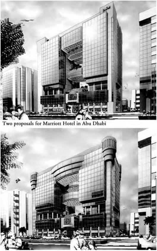
| Types of Construction Drawings Providing accurate construction drawings up front helps ensure that construction projects will proceed in an orderly manner, reducing costly and time-consuming rework by contractors and subcontractors down the line. Construction drawings are generally categorized according to their intended purpose. Types commonly used in construction may be divided into five main categories based on the function they intend to serve: 1. Preliminary drawings 2. Presentation drawings 3. Working drawings 4. Shop/assembly drawings 5. Specialized and miscellaneous drawings Preliminary-Design and Concept Drawings At the initial promotional stages of a project, the architect or designer often prepares preliminary sketches, which are essentially schematic design/concept-development drawings. These provide a convenient and practical basis for communication between the designer and the owner in the idea formulation stage. During the design phase, these drawings go through many alterations, helping the client to determine the most aesthetically attractive and functional design. These drawings are not meant for construction but rather for exploratory purposes, providing an overall concept that reflects the client’s needs, as well as functional studies, materials to be used, preliminary cost estimates and budget, preliminary construction approvals, etc. Preliminary drawings are also typically used to explore with other consultants concepts relating to the mechanical, plumbing, and electrical systems to be provided. These are followed by formal design-development drawings prior to the working-drawing or construction-document stage. Presentation Drawings The purpose of presentation drawings is to present the proposed building or facility in an attractive setting at the proposed site for promotional purposes. They usually consist of perspective views complete with colors and shading, although they may also contain nicely drawn elevation views with shadows and landscaping (Figures 2.7A and B). Presentation drawings are therefore essentially selling tools, a means to sell the building or project before it reaches the working-drawing stage, and are used in brochures and other outlets. This phase is also where the schematic design is developed, finalized, and approved by the client. Working Drawings Also called project and constructions drawings, working drawings include all the drawings required by the various trades to complete a project. These drawings are technical and are intended to furnish all the necessary information required by a contractor to erect a structure. Working drawings show the size, quantity, location, and relationship of the building components. They are typically prepared in considerable detail by the architect or engineer, and the amount of time and effort expended on them comprises a major portion of the consultant’s design services. |
||
| 22 | Chapter 2 | ||
 |
|||
| Figure 2.7A Presentations can play a pivotal role in convincing a client to approve a particular design. In this illustration, two design proposals by the author for a hotel, reflecting different architectural treatments, were submitted to both the client and to Marriott for approval. | |||
| Blueprints and Construction Drawings: A Universal Language | 23 | ||
 |
|||
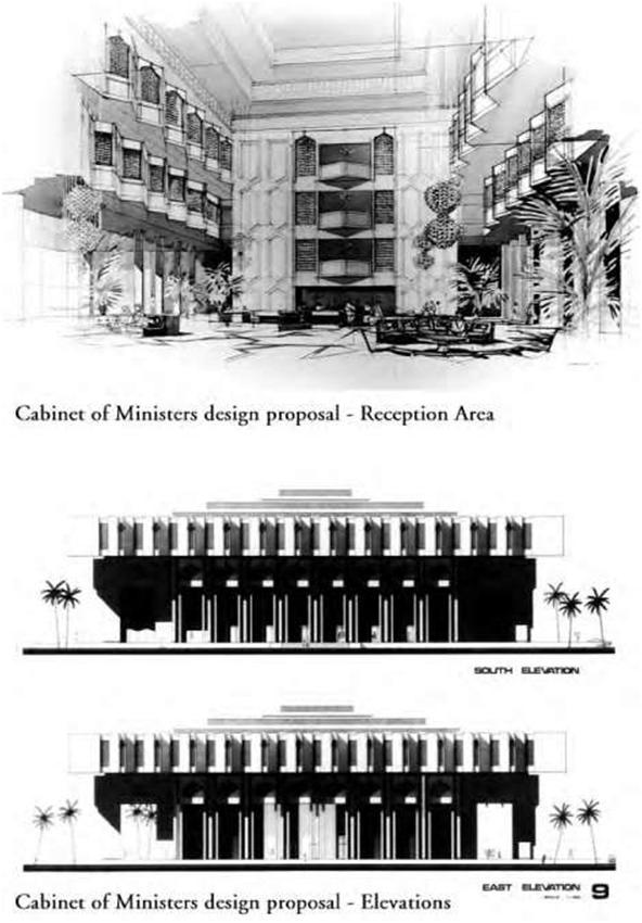
| Figure 2.7B International competition submission for a cabinet of ministers complex in Abu Dhabi by the author that won first prize. | |||
| 24 | Chapter 2 | ||
|
Sometimes the printing may be difficult to read or important information may be missing from the drawings. Occasionally entire pages may be missing, or the contractor may have received only a set of plans or specifications. If the prints are incomplete or of poor quality, the consultant should be immediately notified and asked to address the problem. Working drawings serve many functions: 1. They are the means for receiving a building permit. Before construction begins, the local building authority has to review the working drawings to ensure that they meet required building codes. A building permit will be issued after approval of the drawings. 2. They are used for competitive bidding. They allow contractors to study the documents and make bids based on their review of the drawings and other documents, thus providing the owner with the most economical cost for construction. 3. They provide instructions for construction. Working drawings should contain all the necessary information to build the structure. 4. They are used for material take-offs. Labor, material, and other estimates are made from working drawings prior to commencement of construction. 5. They provide a permanent record for future use (such as remodeling and dispute resolution). 6. They can be used as a basis for leasing purposes. 7. After the project is awarded, the drawings form the basis of the contract between the contractor, subcontractor, and client. The pages in a set of blueprints are usually carefully lettered and numbered. The letters shown here are the ones most commonly used in the industry: A: Architectural pages S: Structural pages P: Plumbing pages M: Mechanical pages E: Electrical pages Thus if a set of blueprints consist of 30 pages, it may be numbered as follows: A1 through A8 (eight architectural pages); S1 through S10 (10 structural pages); P1 through P3 (three plumbing pages);M1 through M4 (four mechanical pages); E1 through E5 (five electrical pages). Shop and Assembly Drawings Shop and assembly drawings are technical drawings prepared by various contractors, subcontractors, and suppliers participating in the construction process to show how their product is to be made. Since many products contain more than one component, shop and assembly drawings (also called fabrication drawings) identify each component and show how they all fit together. These drawings should contain all the necessary information on the size, shape, material, and provisions for connections and attachments for each member, including details, schedules, diagrams, and other related data to illustrate a material, product, or system for some portion of the work prepared by the construction contractor, subcontractor, manufacturer, distributor, or supplier. Product data includes items such as brochures, illustrations, performance charts, and other information by which the work can be evaluated. The infor- |
|||
| Blueprints and Construction Drawings: A Universal Language | 25 | ||
|
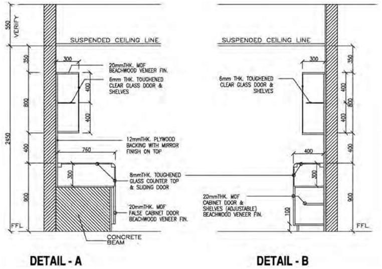
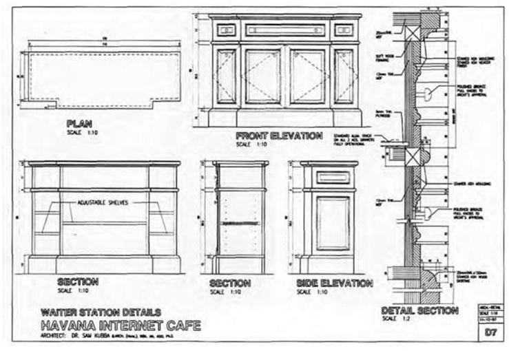
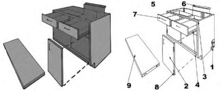
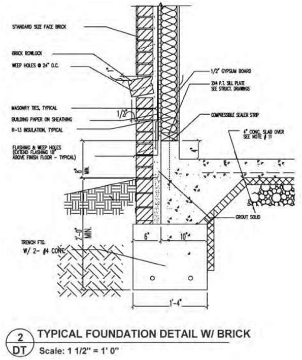
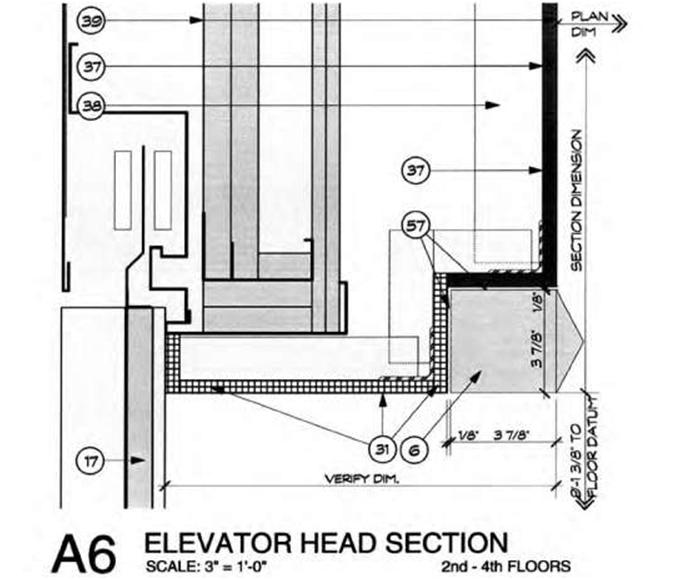
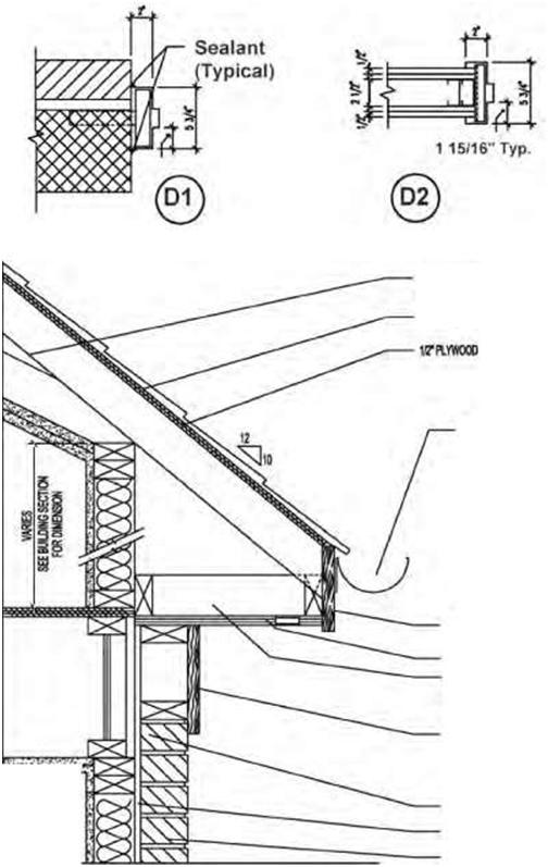
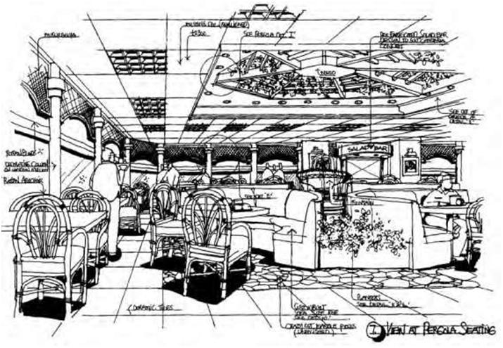
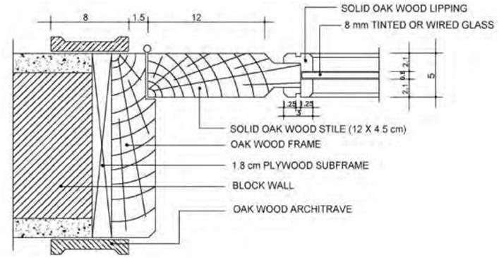
mation provided must be in sufficient detail to permit ordering the material for the product concerned and its fabrication in the shop or yard. In practice the consultant often has to rely on these specialists to furnish precise information about their components. In most projects, whether large or small, contractors and subcontractors are frequently required to draft shop drawings even for minor shop and field projects such as doors, cabinets, and the like. Thus, for example, if complex cabinetwork is required, it must be built to exact size and specifications. A shop drawing becomes necessary to ensure that the cabinetwork will fit into the structure and that the structure will accommodate it. In Figure 2.8A we see shop-drawing details for a restaurant waiter station and Figure 2.8B shows how a cabinet is to be assembled. Approval of the shop drawings usually precedes the actual fabrication of the component. Shop drawings also help the consultant check the quality of other components that subcontractors propose to furnish. Details Detail drawings provide information about specific parts of the construction and are on a larger scale than general drawings. They show features that do not appear at all or are on too small a scale in general drawings. The wall section and elevator details in Figures 2.9A and B are typical examples and are drawn to a considerably larger scale than the plans and elevations. Framing details at doors, windows, and cornices, which are the most common types of details, are nearly always shown in sections. Details are included whenever the information given in the plans, elevations, and wall sections is not sufficiently “detailed” to guide the craftsmen on the job. Figure 2.10 shows some typical door and eave details. A detail contains both graphic and written information. An area of construction is drawn at a larger scale in order to clearly show the materials, dimensions, method of building, desired joint or attachment, and so on. Details are often drawn as sections. It is as if a slice is made through a specific area and the inner components are visible. In Figures 2.11A and B we see an example of a typical bay window detail. There are many types of details, all of which are drawn as needed to clarify specific aspects of a design. A drawing sheet will often show several details. The complexity of the project will determine which areas need to be shown at a larger scale. Details are always drawn to scale. A typical scale for a detail is 3 inches to 1 foot (scale: 3 inches = 1 foot, 0 inches). The scale for each detail will vary depending on how much information is required to make the construction clear to the builder. Each detail will have the scale noted below. Specialized and Miscellaneous Drawing Types There are numerous other types of drawings used by architects and engineers in the construction industry. Freehand sketches are drawings made without the aid of any type of drawing instruments. Sketches can be an extremely valuable tool for architects, designers, builders, and contractors. It is often the quickest and most economical method to communicate ideas (Figures 2.12A, B, and C), construction methods, and concepts or to record field instructions. It is an ideal method to sell an idea to a client and get preliminary approval for a design. Likewise, when installing mechanical or electrical systems and circuits, you may sometimes have to exchange information about your job with others. A freehand sketch can be an accurate and appropriate method to communicate this information. This type of drawing is informal in character, may or may not be drawn to scale, and need not follow any particular format. A |
|||
| 26 Chapter 2 | ||
 |
||
| Figure 2.8A Drawing showing the details for a restaurant waiter station. | ||
|
sketch can be used in many ways. Another example of where to use a sketch is to show a field change that must be made. No matter how well a project is planned, field changes may sometimes need to be made, and a sketch will often go a long way to helping the builder visualize the designer’s intention or the construction techniques to be used. Sketches may include dimensions, symbols, and other information needed to convey your idea of the required change to someone else (such as the project supervisor or project chief). Erection drawings, or erection diagrams, indicate the location and position of the various members in the finished structure. Erection drawings are especially useful to builders performing the erection in the field. The information erection drawings show includes supplying the approximate weight of heavy pieces, the number of pieces, and other helpful data. Framing drawings are necessary to show the layouts and provide other relevant information about the various framing components. These include floor joists, trusses, beam locations, and other structural elements. Framing layouts are drawn to scale but don’t normally get into the details of each stud location in the walls, because framing contractors are required to follow certain rules and regulations to assure that the structure meets the required building-code specifications. |
||
| Blueprints and Construction Drawings: A Universal Language 27 | ||
 |
||
| Figure 2.8B Illustrations showing the components of a cabinet. | ||
|
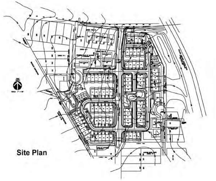
Falsework drawings show temporary supports of timber or steel that are required sometimes in the erection of difficult or important structures. When falsework is required on an elaborate scale, drawings similar to the general and detail drawings already described may be provided to guide construction. For simple falsework field sketches may be all that is needed. Master-plan drawings are commonly used in the architectural, topographical, and construction fields. They show sufficient features to be used as guides in long-range area development and usually contain a considerable amount of information including section boundary lines, contour lines, acreage, existing utilities, rights-of-way and appurtenances, horizontal and vertical control data, locations and descriptions of existing and proposed structures, existing and proposed surfaced and unsurfaced roads and sidewalks, streams, and north-point indicator (arrow). 2.5 TITLE BLOCKS |
||
|
It is standard practice to include a title block on each page of a set of blueprints. It is typically located in the bottom right-hand corner of the drawing frame. Many firms, however, are using customized sheets that extend the title block from the lower right to the upper right-hand side of the sheet (Figure 2.13). The title block should show the name of the project and the drawing and sheet numbers as well as the drawing title (e.g., “site plan”). The drawing number is especially important, both for purposes of filing the blueprint and for locating the correct drawing when it is specified on another blueprint. The title block also typically shows the name of the consultant, architect, engineer, or designer and the signature of the approving authority. The title block should normally show the date the drawing was made and the initials of who made it. This information is important because using an outdated set of drawings can cause serious problems. Any revisions should be noted within the title block. |
||
| 28 | Chapter 2 | ||
 |
|||
| Figure 2.9A AutoCAD drawing showing a typical foundation/wall section detail for a new residence. | |||
| To summarize, the title block should generally contain the following information: Name of the consultant, company, or organization with address and phone number. Title of the drawing. This is an identification of the project by client name, company, or project name. Drawing number. This can be a specific job or file number for the drawing. |
|||
| Blueprints and Construction Drawings: A Universal Language | 29 | |||
 |
||||
| Figure 2.9B Example of an elevator detail for a commercial building produced on VectorWorks/MiniCAD using a Macintosh computer (courtesy Herring and Trowbridge, Architects). | ||||
| • |
Scale. Some consultant firms provide a location for the general scale of the drawing in the title block, although most firms now omit the scale from the title block and place it on the sheet directly below the title of each individual plan, view, or detail. Where more than one scale is used, as is found on detail sheets, the space for indication of scale should read “as noted” or “as shown.” The signature or initials of the drafter, checker, approving officer, and issuing officer, with the respective dates, should be shown. Drawing or sheet identification. Each sheet should be numbered in relation to the entire set of drawings. Thus, if the set consists of ten sheets, each consecutive sheet is numbered 1 of 10, 2 of 10, and so on. Other information as required. |
|||
| • | ||||
| • | ||||
| • | ||||
| 30 | Chapter 2 | |||
 StttO FRIEZE BO. .’.■■■■..!-;;■’*.■■- |
BOOfTRUSSES SEE ROOFFRAMING PLAN SEE STRIP ELEV. FOR ROOF MATERIAL |
A | ||
| KALF ROUND GUTTER (TYP.f | ||||
| W*8 FASCIA BOARD Iff PLYWOOD W<!” VENT (TYR) 2X1 BLOCKING |
||||
| METAL FLASHING SHEATH NG BRKKFACAOEPYP.) | ||||
| EAVE DETAIL (WITH BRICK FACADE) Scale: 1 1/2″ = 1*0″ |
B | |||
| Figure 2.10 Typical AutoCAD-generated door (A) and eave (B) details. | ||||
| Blueprints and Construction Drawings: A Universal Language | 31 | ||
 |
|||
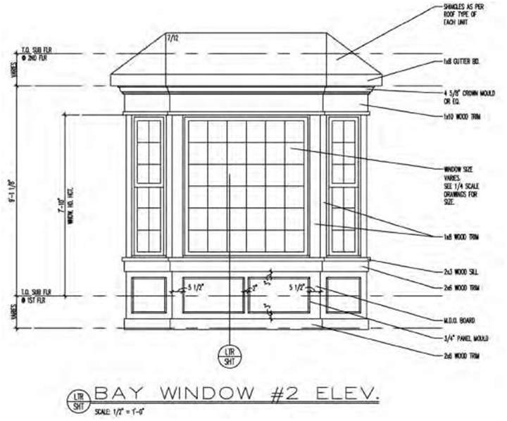
| Figure 2.11A An AutoCAD drawing of a residential bay window showing an elevation. | |||
|
The following information is also normally required in title blocks: the name and location of the activity, the specifications and contract numbers (if any), the preparing activity including the architect-engineer (A-E) firm if applicable, and the surnames of the personnel concerned in the preparation of the drawings. Revision Block Many firms provide a revision column in which drawing changes are identified and recorded. The revision block is usually located in the right-hand comer of the blueprint. All revisions are noted in this block and dated and identified by a letter and an optional brief description of the revision with the initials of the individual making the change (Figure 2.14). If changes are made on the face of the drawing after it has been released for construction, a circle with a revision number or letter should accompany the change. |
|||
| 32 | Chapter 2 | ||
 |
|||
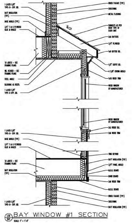
| Figure 2.11B An AutoCAD drawing of a residential bay window showing detail. The information shown on the detail allows the builder to construct the bay window as intended. | |||
| Blueprints and Construction Drawings: A Universal Language | 33 | ||
 |
|||
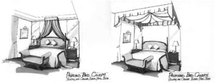
| Figure 2.12A Sketch of a president’s suite bedroom—Crowne Plaza, Abu Dhabi. | |||
 |
|||
| Figure 2.12B Sketch of Havana Internet Cafe, Abu Dhabi. | |||
| 34 | Chapter 2 | ||
 |
|||
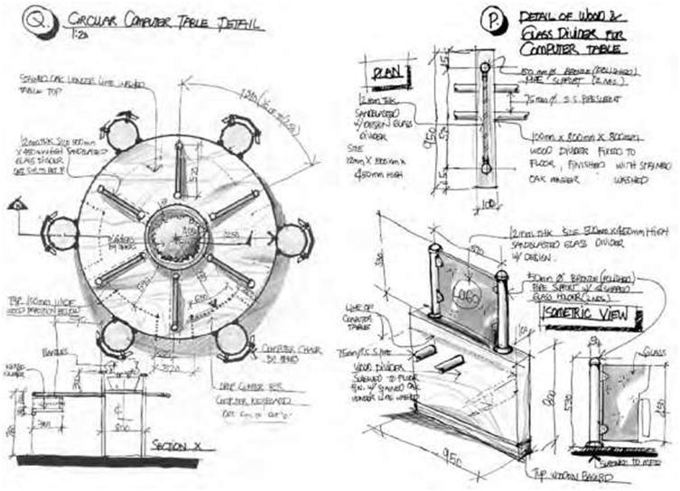
| Figure 2.12C Sketch of computer desk details, Havana Internet Cafe, Abu Dhabi. | |||
| Scale The graphic representation of the project is drawn to some proportion of the actual size of the project; usually 1/8 inch is equal to a foot. Although the original drawing may be scaled accurately, the print will be a copy of that original and is not likely to be the same size as the original drawing. The copy may have been reduced slightly. Likewise, the paper size is often affected by temperature and humidity and may therefore stretch or shrink. Due to these and other factors, avoid relying on measurements taken by laying a rule on the drawing. |
|||
| Zoning For large projects, a drawing may sometimes be divided into a grid using letters and numbers. When zoning is used, it is typically located inside the drawing frame. Zoning allows easy reference to various parts of the drawing by referencing a coordinate such as B4. |
|||
| Blueprints and Construction Drawings: A Universal Language | 35 | ||
 |
|||
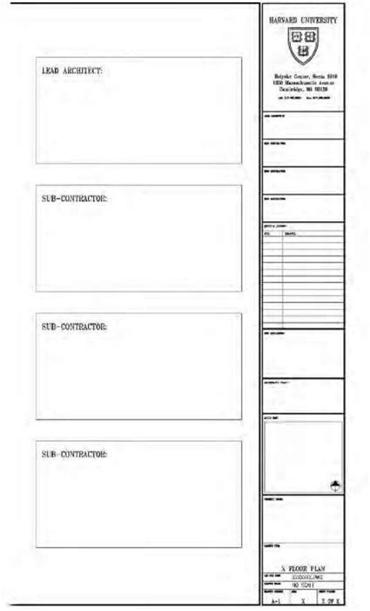
| Figure 2.13 Cover sheet including title block used by Harvard University on its working drawing documents. | |||
| 36 | Chapter 2 | ||
 |
|||
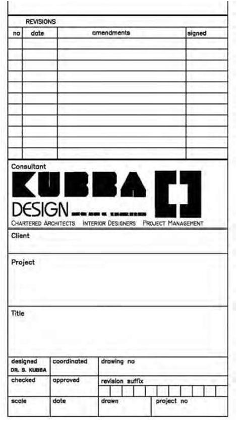
| Figure 2.14 Title block showing position of revision block on a consultant’s typical working drawings. | |||
| 3 | |||
| Understanding Line Types | |||
| 3.1 INTRODUCTION—THE ALPHABET OF LINES | |||
|
The alphabet of lines is the universal language of the technician, architect, and engineer. In reality, lines are the basis of all construction drawings. To read and understand blueprints, you need to understand the use of lines. By combining lines of different thicknesses, types, and lengths, it is possible to graphically describe objects in sufficient detail to allow a person with a basic understanding of blueprint reading to accurately visualize their size and shape. As will be explained, line characteristics such as width, breaks, and zigzags all have meaning, and each line has a specific design and thickness that distinguishes it from other lines. Drafting is an international graphic language that uses lines, symbols, and notes to describe a structure to be built, and lines themselves are expressive tools on well-executed drawings. Certain lines are drawn thick so they stand out clearly from other information on the drawing, whereas other lines are drawn thin. Thin lines are not necessarily less important than thick lines, but they are subordinate for identification purposes. Drawings with only lines of the same intensity are often difficult to interpret and usually monotonous to read. As mentioned in Chapter 1, there are a number of organizations such as the American National Standards Institute (ANSI) and the International Organization for Standardization (ISO) that have voluntarily adopted certain drafting standards that are generally accepted and widely used around the world. 3.2 LINE WEIGHTS AND TYPES |
|||
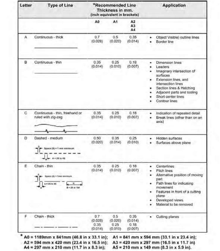
| Line weights are generally subject to the following conventions: 1. For manual pencil drafting using drawing boards, finished work includes bold object lines (2H to B pencils), light dimension lines, center lines, section lines, and so on (3H to 5H pencils). Temporary construction lines, guidelines for lettering, and other types should be kept very light (7H or 8H). Border lines for the drawing sheet and title block should be made bold (3B to 6B). 2. For inked or computer-plotted drawings different pen widths are used to achieve similar effects (see Figure 3.1). When plotting (printing) using a laser or inkjet printer from a computer drawing in |
|||
| Copyright © 2009 by The McGraw-Hill Companies, Inc. Click here for terms of use. | 37 | ||
| 38 | Chapter 3 | ||
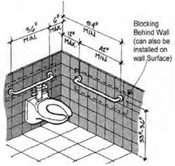
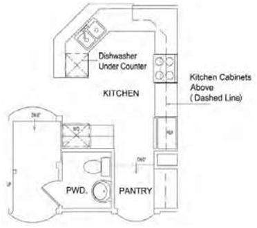
| AutoCAD, these line-boldness conventions are replicated by configuring each line color as certain line widths. 3. Border lines are roughly twice as bold as object lines, which in turn are roughly twice as bold as dimension lines. In addition, AutoCAD drafting uses colors to emulate each thickness (black or white for objects, green for dimensions, blue for borders, etc.). In AutoCAD’s print-dialogue box you are allowed to designate different line widths for each different color. Line Types: The major line types and line thicknesses using pens or plotter machines are outlined below. It becomes obvious from the table below that larger sheets require the use of thicker lines than smaller sheets. Object Lines Object lines, also known as visible lines, are solid lines used mainly to define the shape and size of a structure or object. They are continuous prominent lines representing the edges of surfaces or the intersection of two surfaces, as shown in Figure 3.2. An object/visible line is typically drawn thick (dark) and solid so that the outline or shape of the object (e.g., wall, floor, elevation, detail, or section) clearly stands out on the drawing with a definite contrast between these lines and secondary lines on the drawing. They are heavier than hidden lines, dimension lines, center lines, and broken lines. As we shall see later in the chapter, blueprint drawings often contain different solid line types that are not object lines. Dashed Lines Dashed or hidden lines serve more than one purpose in construction drawings. They are comprised of medium- or light-weight, uniformly sized broken lines consisting of evenly spaced short dashes and are generally intended to represent hidden surfaces or intersections of an object. On floor plans they may be used to represent features that lie above the plane of the drawing, such as high wall cabinets in a kitchen. You may vary the lengths of the dashes slightly in relation to the size of the drawing. On remodeling-job drawings, they are also used to indicate the position of preexisting construction. In some cases they are used for relationship clarification or to show alternative positions of a movable component. To be complete, a drawing must include lines that represent all the edges and intersections of the surfaces in the object. Many of these lines are invisible to the observer because they are covered by other portions of the object. For example, in Figure 3.3A the dashed lines indicate the location of blocking hidden behind the wall. In architectural drafting dashed lines may be applied in different weights to reflect their purpose (e.g., to reflect importance or distance from the main view) while showing drawing features that are not visible in relationship to the view or plan. These dashed features can be subordinated to the main emphasis of the drawing. Hidden lines should typically begin and end with a dash, in contrast with the visible lines from which they start, except when a dash would form a continuation of a visible line. Dashes should be joined at comers; likewise, arcs should begin with dashes at tangent points. Hidden lines should be omitted when not required for the clarity of the drawing. Although features located behind transparent materials may be visible, they should be treated preferably as concealed features and shown with hidden lines. Examples of dashed-line representations include beams and headers, upper kitchen cabinets, un-dercounter appliances (e.g., dishwasher or refrigerator), or electrical circuit runs, as shown in Figure 3.3B. Figure 3.3C is another example of hidden-line use. |
|||
| Understanding Line Types | 39 | ||
 |
|||
|
Figure 3.1 Major types of line used in construction drawings. Line weights are clearly impacted by sheet size. The larger the sheet being used, the heavier the line weight required. An object line on an AO sheet for example should be twice as thick as an object line drawn on an A2, A3, or A4 sheet. |
|||
| 40 | Chapter 3 | ||
 |
|||
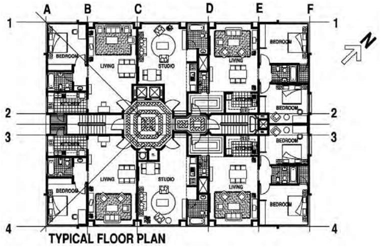
| Figure 3.2 Object lines identify and describe the shape of an object. For example, in this drawing object lines are used to portray the furniture as well as the various architectural elements in the design (e.g., stairs, elevators, walls, etc). | |||
| Section Lines Section lines (also called cross-hatch lines) indicate the cut surface in a section view. They usually consist of fine linework (thinner than object lines), typically angular (45 degrees), giving a tone to sectioned surfaces (Figures 3.4A and B. Section lines are used to emphasize the cutting-plane surface and make the view easier to visualize. |
|||
| Center Lines Center lines consist of thin (light), broken lines of alternating long and short dashes. They are used to identify the centers of symmetrical objects such as a column, wall, or window. Center lines are also used to indicate the center of a whole circle or part of a circle and to show that an object is symmetrical about a line (Figures 3.5A and B). The symbol is typically drawn as such: (C/L). Center lines are symmetrical on the axis of circular features and are also used to locate centers of windows and door symbols on floor plans. |
|||
| Understanding Line Types | 41 | ||
 |
 |
||
| Figure 3.3A Hidden lines represent invisible edges and surfaces—in this case, blocking hidden behind a wall. | Figure 3.3B Hidden lines here represent an undercounter appliance and hung kitchen wall cabinets. | ||
 |
|||
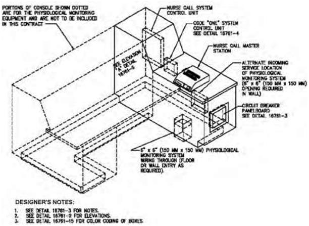
| Figure 3.3C An illustration of a nurses’ console showing extensive use of hidden lines. | |||
| 42 | Chapter 3 | ||
 |
|||
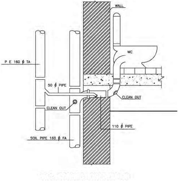
| W.C. CONNECTION DETAILS Figure 3.4A Sectional lines add emphasis to the walls in this illustration. |
|||
|
The long dashes of center lines may vary in length, depending upon the size of the drawing. Center lines should begin and end with long dashes, and they should not intersect at the spaces between the dashes. They should extend uniformly and distinctly a short distance beyond the object or feature of the drawing unless a longer extension line is required for dimensioning or for some other purpose. Very short center lines may be unbroken if there is no confusion with other lines. Symmetry lines are center lines used as axes of symmetry for partial views. To identify the line of symmetry, two thick, short parallel lines are drawn at right angles to the center line. Symmetry lines are |
|||
| Understanding Line Types | 43 | ||
 |
|||
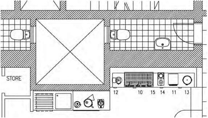
| Figure 3.4B Sectional lines add emphasis to the walls in this illustration. | |||
| used to represent partially drawn views and partial sections of symmetrical parts. Symmetrical-view visible and hidden lines may be extended past the symmetrical line if this improves clarity. | |||
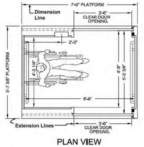
| Extension Lines Extension lines are used in dimensioning to show the size of an object. Extension lines are thin, dark, solid lines that extend from an object at the exact locations between which dimensions are to be placed. A space of approximately 1/16 inch is usually allowed between the object and the beginning of the extension line (Figure 3.6). Plan to avoid crossing other extension lines and/or dimension lines. Extension lines are fine lines that relate the dimension lines to their features. They do not touch the features; instead they start about 1/6 inch (4.23 mm) from the feature and extend about 1/8 inch (3.175 mm) beyond the arrowheads of the dimension line. Extension lines show the extent of a dimension, and dimension lines show the length of the dimension and terminate at the related extension lines with slashes, arrowheads, or dots. The dimension number in feet and inches is placed above and near the center of the solid dimension line. |
|||
| 44 | Chapter 3 | ||
 |
|||
| ELEVATION Figure 3.5A Center lines indicate the centers of circles, arcs, and symmetrical objects. |
|||
| Dimension Lines Dimension lines are solid lines similar in weight to extension lines that are used to indicate length. They are drawn from one extension to the next, representing the distance between the extension lines. Once the external shape and internal features of a part are represented by a combination of lines, further information is provided by dimensions. Fractional, decimal, and metric dimensions are used on drawings to give size descriptions. Each of these three systems of dimensioning is used throughout the text. Dimension lines are fine lines that are often broken at the dimension and ending with arrowheads, dots, or a small diagonal line (Figures 3.6, 3.7A and B). The tips or points of these arrowheads indicate the exact distance, referred to by a numerical dimension placed either at a break in the line or directly above the lines near their center. |
|||
| Understanding Line Types | 45 | ||
 |
|||
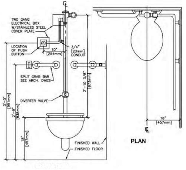
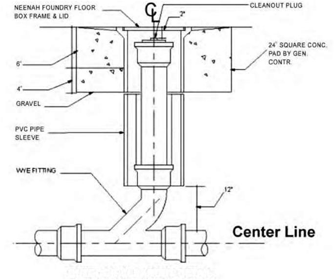
| OUTDOOR CLEANOUT DETAIL Figure 3.5B Center lines indicate the centers of circles, arcs, and symmetrical objects. |
|||
|
Different types of arrowheads are used in dimensioning. The point or tip of the arrowhead touches the extension line. The size of the arrow is determined by the thickness of the dimension line and the size of the drawing. Closed and open arrowheads are the two shapes generally used. The closed arrowhead is preferred. The extension line usually projects 1/16 inch beyond a dimension line. Any additional length to the extension line is of no value in dimensioning. When dimensions can be added together to come up with one overall dimension, they are known as chain dimensions. Chain dimensions are usually expressed in a single line whenever possible (Figure 3.7B). |
|||
| 46 | ||
 |
||
| Figure 3.6 Extension lines are typically used for dimensioning. | ||
| Phantom Lines Phantom lines are thin, dark lines that consist of a long dash and two short dashes. They look like cutting-plane lines except that they are lighter. Phantom lines are used mainly to show alternative positions of fixtures, movable partitions, motion (e.g., alternative door swings) or future construction additions (as well as existing structures to be removed). They are also used to indicate repeated details and materials prior to machining. Leader Lines and Arrowheads Leader lines are fine lines terminating with an arrowhead or dot at one end to relate a note or callout to its feature. They are often drawn at an angle or straight from the principal lines on the drawing or in a free-curved manner to distinguish them easily from object lines. Leader lines are used to label elements by connecting an object to a note or abbreviation or a dimension to the object it represents on a drawing (Figures 3.8A, B, and C). |
||
| Understanding Line Types | 47 | ||||||
 |
|||||||
 |
^=^m |  |
|||||
 |
13+0 | ||||||
| 42 tO | . 1550 ,960 , 1530 tP—————*-^——iF—————*- | 6950 | |||||
| 17630 | |||||||
| CROWN PLAZA RESIDENCE | B | ||||||
| Figure 3.7 A. Dimensions terminated with dots. B. Example of a chain-dimensions line. | |||||||
| Cutting-Plane and Viewing-Plane Lines These are very prominent broken lines (usually two dots and a dash) that are used to show the location of cutting planes for sectional views. Arrows on their ends indicate the direction in which the section is observed (Figure 3.9A). Lines or circular symbols are sometimes used at their ends to relate the cutting planes to their section views. Like property lines, these lines are normally heavier than any other lines on a drawing. |
|||||||
| 48 | Chapter 3 | |||
 |
A | |||
 |
B | |||
| xlx Figure 3.8A,B Examples of leader lines terminating with arrowheads. | ||||
| Understanding Line Types | 49 | ||
 |
|||
| Figure 3.8C Example of a leader line terminating with a dot. | |||
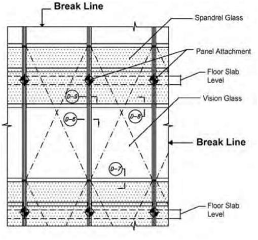
| Break Lines These are fine straight lines with zig-zag-zig offsets to show a break or termination of a partial view or to omit portions of an object. Architects frequently use break lines to eliminate unimportant portions of details, thus allowing the important portions to be made larger. They are also used on detail and assembly drawings. Small break lines are often fine, ragged lines. A straight, thin line made with freehand zigzags is used for long breaks, a thick freehand line for short breaks, and a jagged line for wood parts. Special breaks may be used to show cylindrical and tubular parts and to indicate that an end view is not shown; otherwise, the thick break line is typically used. The type of break line normally associated with architectural drafting is the long break line. Break lines are used to terminate features on a drawing when the extent of the feature has been clearly defined. Contour Lines These are fine lines that are used mainly to delineate variations in a site’s elevation. If a site is fairly level, there will be few if any contour lines on the drawing, whereas if it has a significant slope, it is likely that the plot plan will show a number of contour lines. Sometimes a model is used to depict the topography of a site (Figure 3.11). Property Lines Property lines define the boundaries of a property. These lines are normally heavier than other lines on site or plot plans. |
|||
| 50 | Chapter 3 | |||||
| rh | Cover as per schedule Refer to Structural Drwg,
|
|||||
| Incoming | ||||||
| -he: | -.-.^Pl | ^B-l | ||||
| UPVC Backdrop | ||||||
| kM y-°- Un | ||||||
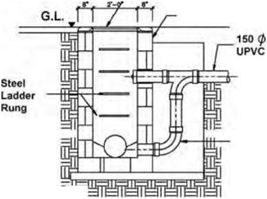
| PLAN | iihh section a-a Backdrop and manhole detail |
A | ||||
 |
B | |||||
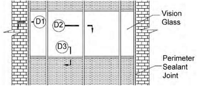
| Figure 3.9A,B Examples of cutting-plane lines. | ||||||
| Understanding Line Types | 51 | ||||
 |
A | ||||
| Bent Plate 1/4 in x 4 in x 4 in x 6 in (6mm x 100mm x 100mm x 150mm) | |||||
| Break Lines | 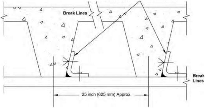 Break Lines |
B | |||
| Break | |||||
| Lines <> | |||||
| Figure 3.10A,B Examples of the use of break lines. | |||||
| 52 | Chapter 3 | ||
 |
|||
| Figure 3.11 Illustration of a model showing the topography of the site. | |||