
| 4.1 TYPES OF DIMENSIONS | |||
|
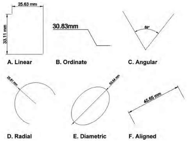
A dimension is a numerical value expressed in an appropriate unit of measure. It is indicated on drawings along with lines, arrows, symbols, and notes to define the size and specification of an object. Dimensioning is thus a process of incorporating numerical values onto a drawing to enable the sizing of different elements and the location of parts of a building or object. Drawings should be fully dimensioned so that a minimum of computation is required and all the parts can be built without having to scale the drawings to determine an object’s size. Duplication of dimensions should whenever possible be avoided unless it adds clarity. Figure 4.1 shows examples of different types of dimensions. Distances may be indicated with either of two standardized forms of dimension: linear and ordinate. Linear Dimensions are used for displaying and measuring length along the X or Y axis. As the name suggests it can only be aligned along the X or Y axis. These dimensions are typically used to show absolute lengths along the X or Y axis (Figure 4.1A). With linear dimensions, there are two parallel lines, called “extension lines,” that are spaced at the distance between two features and shown at each of the features (Figure 4.2A). The dimension line consists of a line perpendicular to the extension lines; it is shown between the extension lines and terminates at these lines typically with arrows, slashes, or dots. (For examples of different endpoints see Figures 4.2A, 4.2B, and 3.8C.) The distance is indicated numerically at the midpoint of the dimension line, either adjacent to it or in a gap provided for it. Ordinate dimensions are used for measuring the length along any X or Y axis and displaying length as a text with the use of a leader. Generally, these dimensions are used to show lengths of entities using leader lines (Figure 4.1B). Radial Dimensions are used for measuring the radius of arcs, circles, and ellipses and displaying it with a leader line. Radial dimensions often use an “R” followed by the value for the radius (Figure 4.3); Diametral dimensions generally use a circle with a forward-leaning diagonal line through it, called the diameter symbol, followed by the value for the diameter. A radially aligned line with arrowhead pointing to the circular feature, called a leader, is used in conjunction with both diametral and radial dimensions. All types |
|||
| Copyright © 2009 by The McGraw-Hill Companies, Inc. Click here for terms of use. | 53 | ||
| 54 | Chapter 4 | ||
| of dimensions are typically composed of two parts: the nominal value, which is the “ideal” size of the feature, and the tolerance, which specifies the amount that the value may vary above and below the nominal. The Metric System The metric system originated in France in the 1790s as an alternative to the traditional English units of measurement. It was intended to standardize the units of measurement to assist in the expansion of trade and commerce throughout continental Europe. Today the majority of countries around the world have adopted an exclusively metric system of measurement. The United States, however, remains one of the few countries that have not adopted this system. It is expected that the construction industry will eventually convert to the metric system. Some of its many advantages include the elimination of fractions on drawings, simpler calculations, and international uniformity. Dimension Conventions There are a number of conventions that relate to dimensioning that the drafter and blueprint reader should be aware of: |
|||
 |
|||
| Figure 4.1 A diagram showing the different types of dimensions. | |||
| Understanding Dimensions | 55 | ||
 |
|||
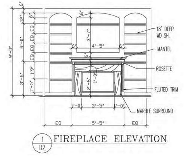
| Figure 4.2A A drawing of a fireplace elevation showing various dimensions including a chain dimension that is outside the smaller dimensions. | |||
|
1. Dimension lines are generally continuous with the number being centered and slightly above the line. Alternatively, the dimension line is broken (typically on engineering drawings), and the numerical dimension is positioned in the break. 2. Both feet and inches need to be shown (e.g., 10 feet, 6 inches). Even if the dimension has no inches, the zero remains as part of the designation (e.g., 10 feet, 0 inches). 3. When dimensions are small (less than 1 foot), only inches are used. 4. Overall or chain dimensions are placed outside the smaller dimensions (Figure 4.1). 5. Arrowheads, dots, or slashes are placed at the extremities of dimension lines to indicate the limits of the dimension (Figures 4.2A, 4.2B, and 3.8C). 6. Dimensions reflect actual building sizes irrespective of the scale used. |
|||
| 56 | Chapter 4 | ||
| 7. Where grid lines are used on a drawing (such as on a modular drawing), it is not necessary to dimension all the grids. Only one grid is normally dimensioned. 8. Similar dimensions need not be duplicated on the various views. 9. Door dimensions may be indicated in the floor-plan symbols or given in a door schedule. 10. Curved or angular leaders are often used to eliminate confusion with other dimension lines. 11. Dimensions showing location are given to centerlines of doors and windows on plan views. 12. To avoid costly mistakes, it is strongly advised to study all the information available before making a determination regarding the dimensions in question. Check that there is no conflict or discrepancy with the information shown in other views. 4.2 USING SCALES |
|||
|
Because building projects are too large to be drawn to actual size on a sheet of paper, everything needs to be drawn proportionately smaller to fit. The views in a set of blueprints are normally drawn at a reduced scale by the drafter. Scale notations are given with each drawing. The scale of a drawing is usually noted in the title block or just below the view when it differs in scale from that given in the title block. When drawing buildings to a specific scale, the drawings retain their relationship to the actual size of the building or object using a simple ratio. This practice of using an accepted standard ratio between full size and what is seen on the drawings is referred to as scale. The scale used on construction drawings depends on: 1. The actual size of the building or object. 2. The amount of detail required to be shown. 3. The size of sheet selected for the drawing. 4. The amount of dimensioning and notation needed. 5. Common practices that regulates certain scales (e.g., normal residential structures are generally drawn at ¼ inch = 1 foot, 0 inches). Scales require distinct machine-divided markings coupled with sharp edges to achieve accurate measurements. The shape of the scales may be triangular, flat, or beveled, and they come in various sizes: they are generally about 12 inches in length although 6-inch scales are also available (Figure 4.4). The three commonly used drawing scales for reading construction drawings and for the development of plans are: the architectural scale, the engineering scale, and the metric scale. Many architects and engineers include a statement on their drawings stating that “dimensions shown on the plans take precedence over scaling.” Some of the problems associated with scaling a drawing include size changes due to reproduction methods, last-minute forced dimension changes, and varying degrees of drafting accuracy depending on the skills of the drafter. Architect’s Scale Architectural scales are normally flat or triangular in shape and come in different lengths, the 12-inch (30-cm) triangular shape being the most popular. All three sides of the triangle scale (except those with a 12-inch scale) contain two scales on each usable surface. Each of these scales uses the full |
|||
| Understanding Dimensions | 57 | ||
 |
|||
| Figure 4.2B A drawing showing dimension lines terminating at the extension lines with arrows at the endpoints. Figure 4.1 shows slashes at the endpoints, and Figure 3.8C shows dots at its end points. | |||
| 58 Chapter 4 | ||
 |
||
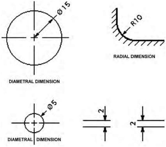
| Figure 4.3 A drawing with examples of diametral and radial dimensions. | ||
|
length of the instrument: one is read from left to right and the other from right to left. Likewise, a scale is usually either half or double that of the scale it is paired with. For example, if one end is a 1/8-inch scale, the opposite end is a 1/4-inch scale; the opposite end of a 1 1/2-inch scale would be a 3-inch scale. The scales are designed to measure feet, inches, and fractions of an inch. Below are the most common scales found on the triangular architect’s scale with their approximate metric equivalent in parentheses: 1/32 inch = 1 foot (1/400 metric equivalent—often used for site plans—actual 1/384) 1/16 inch = 1 foot (1/200 metric equivalent—often used for large projects and small site plans— actual 1/192) 1/8 inch = 1 foot (1/100 metric equivalent—actual 1/96) 1/4 inch = 1 foot (1/50 metric equivalent—actual 1/48) |
||
| Understanding Dimensions | 59 | ||
 |
|||
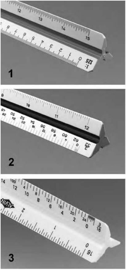
| Figure 4.4A An Illustration showing different triangular scales. | |||
| 60 | Chapter 4 | ||
 |
|||
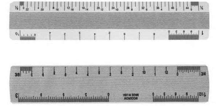
| Figure 4.4B An Illustration of 6-inch scales. | |||
 |
|||
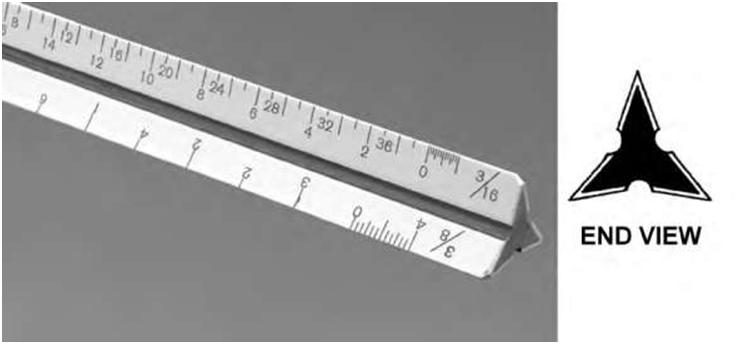
| Figure 4.4C A typical architect’s scale showing end view. | |||
| Understanding Dimensions | 61 | ||
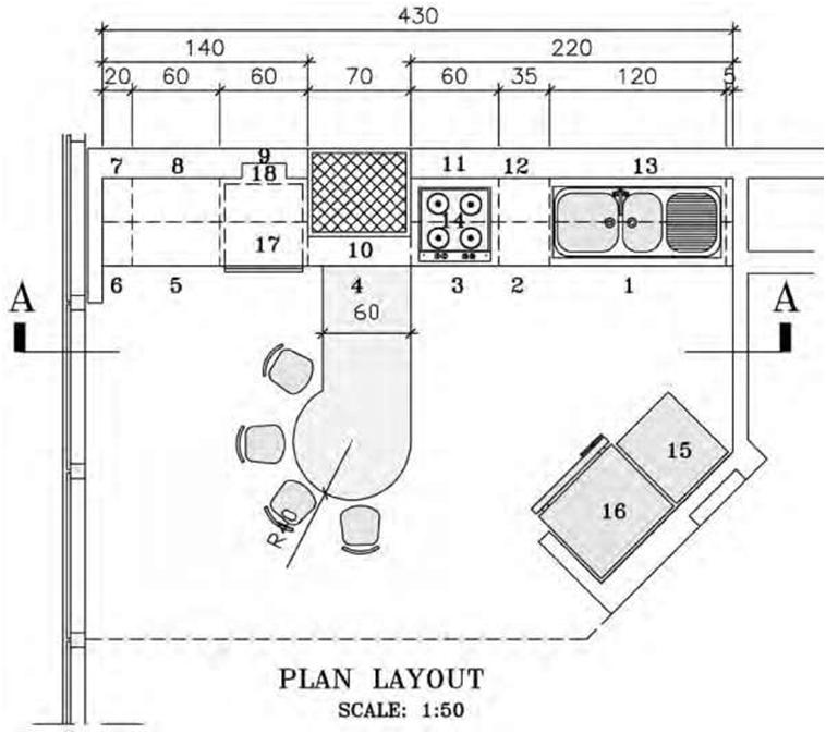
| 3/8 inch = 1 foot (no precise metric equivalent—actual 1/32) 1/2 inch = 1 foot (1/20 or 1/25 metric equivalent—actual 1/24) 3/4 inch = 1 foot (no precise equivalent—actual 1/16) 1 inch = 1 foot (one-twelfth full size—approximate equivalent 1/10) 1 1/2 inches = 1 foot (one-eighth full size) 3 inches = 1 foot (one-quarter full size) As an example, when used on a typical floor plan that is 1/8-inch scale, each 1/8 inch on the drawing represents 1 foot of actual size. The same applies for a 1/4-inch scale in that each 1/4-inch segment on the drawing represents 1 foot of actual size. The same approach applies to other scales. There is no strict convention for which scale is used on which drawings, although certain parts of a set of drawings are traditionally drawn to certain scales. For example, most floor plans and elevations are in 1/8- or 1/4-inch scale, depending on the size of the building and sheet. For residential structures, the 1/4-inch scale is usually used, roughly equivalent to 1:50 in metric scale (Figure 4.5). For large commercial buildings, smaller scales may be used. Exterior elevations are often drawn to 1/4-inch scale. Sections and cross-sections may be drawn to 1/4-, 1/2-, or 3/4-inch scale if the section is complex. Depending on the amount of information presented, construction details can vary from 1/2- to 3-inch scale and even full-size scale for certain millwork details (Figure 4.6). Civil Engineer’s Scale The engineer’s scale is typically used to measure distance on site and land-related plans such as construction site plans, among other uses. Land measurement on site and plot plans differs slightly from measurement on building structures. It is conventional to show land measurement in feet and decimal parts of a foot, carried out to three places (55.478 feet) without the use of inches. Most engineering scales are physically very similar and are based on the same principles as the architectural scales, except that measurements are divided into tenths, twentieths, etc., rather than halves, quarters, and eighths. The engineer’s scale has six scales: 10, 20, 30, 40, 50, and 60. Other specialty scales are divided into even small increments such as 100. The 10 scale refers to 10 feet per inch; the 20 scale is 20 feet per inch, and so on. Sometimes the architect or engineer may include a detail strictly for visual clarification. These details are labeled “NTS” (meaning “not to scale”). This basically means that the detail is for illustration purposes only and not for extracting quantities and measurements. Metric Scales According to the American National Standards Institute (ANSI), the International System of Units (SI) linear unit commonly used on drawings is the millimeter. The American National Metric Council, in its publication American Metric Construction Handbook, recommends the following with reference to metric drawings: 1. Architectural working drawings are to be dimensioned in millimeters (mm) and meters (m). 2. Plot plans and site plans are to be dimensioned in meters (m) or possibly kilometers (km), depending upon the scale, with accuracy to only three decimal places. |
|||
| 62 | Chapter 4 | ||
 |
|||
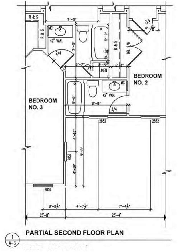
| Scale: 1/4″ = l’-O’ Figure 4.5A A drawing showing scales in imperial (1/4″ = 1′-0″). | |||
| Understanding Dimensions | 63 | ||
 |
|||
| Figure 4.5B A drawing showing scales in metric (1:50). | |||
| 3. No periods are used after the unit symbols. 4. Scale on drawings is to be shown by a ratio (1:1, 1:10, 1:50, etc.). The preferred method of metric dimensioning is called a soft conversion, in which common metric modules are used. Thus, 2-x-4 lumber is 40 x 90 mm using soft conversion. This method is far more convenient when drawing plans and measuring in construction. When measuring plywood thickness in met- |
|||
| 64 | Chapter 4 | ||
 |
|||
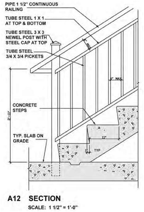
| Figure 4.6A A drawing of a stair detail drawn to a scale of 1 1/2″ = 1′-0″. | |||
|
ric units, 5/8 inch thick equals 17 mm and 3/4 inch thick equals 20 mm. Using the same method, the length and width of sheet of plywood change from 48 x 96 inches to 1200 x 2400 mm. In countries that have adopted the metric system, the dimensioning module is 100 mm, whereas in the United States architectural design and construction modules normally used are 12 or 16 inches. Thus, construction members that are spaced 24 inches on center (O.C.) in the United States translate into 600 mm O.C. spacing in Canada or the United Kingdom. |
|||
| Understanding Dimensions | 65 | ||
 |
|||
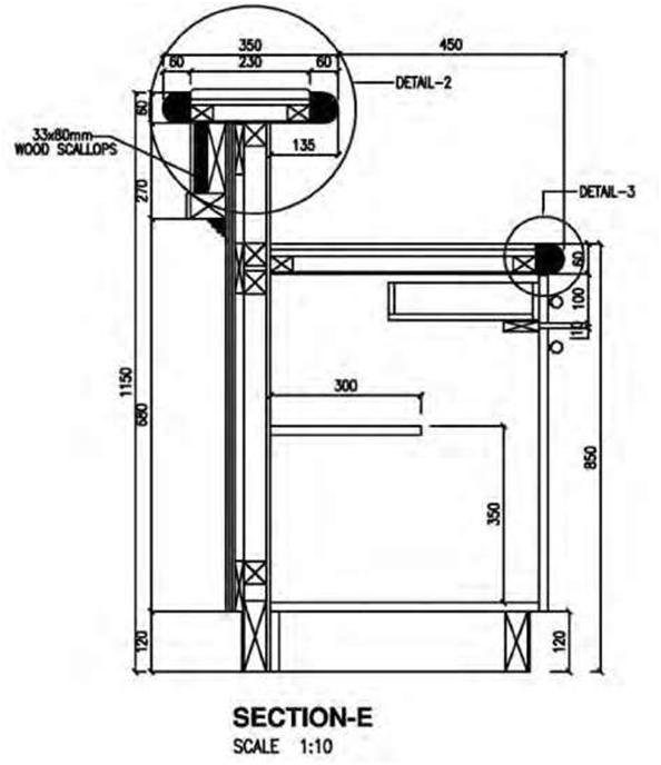
| Figure 4.6B A drawing of a counter detail drawn to a metric scale of 1:10. | |||
|
When reading metric dimensions on a drawing, all dimensions within dimension lines are normally in millimeters, and the millimeter symbol (mm) is omitted unless more than one dimension is quoted, in which case the symbol (mm) is included after the last dimension. Drawings produced in metric, such as floor plans, elevations, and sections, are normally drawn to a scale of 1:50 or 1:100, as opposed to the 1/4 inch = 1 foot, 0 inches or 1/8 inch = 1 foot, 0 inches scale used in the imperial system. Figure 4.5 shows examples of drawings drawn to 1:50 and 1/4 inch = 1 foot, 0 inches scales. |
|||
| 66 | Chapter 4 | ||
| Indication of Scale The scale should normally be noted in the title block of a drawing. When more than one scale is used, they should be shown close to the views to which they refer, and the title block should read “scales as shown.” If a drawing uses predominantly one scale, it should be noted in the title block together with the wording “or as shown.” |
|||
| 4.3 LINEAR DIMENSIONS | |||
|
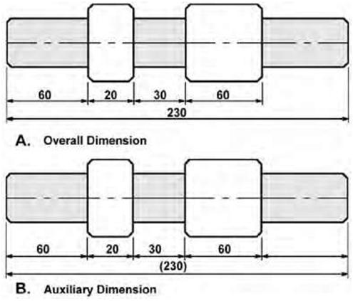
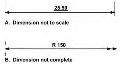
Linear dimensions, or linear units, are used to measure the distance between two points. Since two points define a line, the units of distance are sometimes called “linear” units or dimensions. In the metric system linear dimensions are generally in millimeters. To avoid having to specify “mm” after every dimension, a label such as “all dimensions in mm” or “unless otherwise stated all dimensions are in mm” is usually contained in the title block. If the dimension is less than one, a leading zero should be used before the decimal point: e.g., 0.5. Linear units can also be in centimeters and inches, meters and feet, or kilometers and miles, to name a few. In architectural and engineering drawing, the most important dimensions determine subsequent dimensions, providing a dimension standard. Thus, if a wall is dimensioned to its center first, all following dimensions using this wall as a reference point should be dimensioned at the center. Projection lines are used to indicate the extremities of a dimension. Dimension lines are used to label a particular dimension. Thin lines are used for both projection lines and dimension lines (Figure 4.7). Area dimensions are two-dimensional and measure area. They are often but not always expressed as squares of linear dimensions: square inches or inches squared (in2), square feet or feet squared (ft2), and square meters or meters squared (m2). A rectangle that is 8 feet long by 4 feet wide, for example, has an area of 32 square feet (8 linear feet times 4 linear feet). Examples of units of area that are not a square of a linear unit are the acre and hectare. There are others. Volume dimensions are three-dimensional and are expressed as the cube of linear units. A cube that measures 2 feet on each edge has a volume of 2 x 2 x 2 = 8 cubic feet. Two methods of dimensioning are in common use: Unidirectional: The dimensions are written horizontally. Aligned: The dimensions are written parallel to their dimension lines. Aligned dimensions should always be readable from the bottom or the right of the drawing. When several dimensions make up an overall length, the overall dimension may be shown outside the component dimensions. When specifying an overall dimension, one or more noncritical component dimensions must be omitted (Figure 4.8A). When all of the component dimensions must be specified, an overall length may still be specified as an auxiliary dimension. Auxiliary dimensions are never toleranced and are shown in brackets (Figure 4.8B). Dimensions that are not drawn to scale are underlined (Figure 4.9A). When a dimension line cannot be completely drawn to its normal termination point, the free end is terminated in a double arrowhead (Figure 4.9B). |
|||
| Understanding Dimensions | 67 | ||
 |
|||
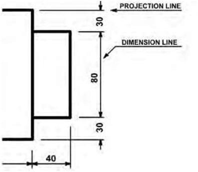
| Figure 4.7 A diagram showing the use of projection and dimension lines. | |||
 |
|||
| Figure 4.8 Two line drawings depicting the use of overall dimension (A) and auxiliary dimension (B). | |||
| 68 | Chapter 4 | ||
| 4.4 ANGULAR DIMENSIONS | |||
|
Angular dimensions are used for measuring and displaying inside and outside angles. These angles are measured in degrees (Figure 4.1C). Where greater accuracy is required, the degree is divided into 60 minutes and the minute into 60 seconds. For reference, a circle has 360 degrees. Inch and millimeter measurements both measure angles in degrees. Normally, angular dimensions are specified in decimal degrees, degrees and minutes, or degrees, minutes, and seconds (For example, 24.5°, 24° 30′, 24° 30′ 16″). When the angle is less than 1 degree, a leading zero should be used (for example, 0.5°, 0° 30′). 4.5 REFERENCE DIMENSIONS |
|||
|
A reference dimension is used only for information purposes. The indication “REF” should be noted immediately under or beside the dimension. Normally it is either a duplication of a dimension or the accumulated value of other dimensions. Reference dimensions are typically located within parentheses. Reference dimensions do not have tolerances and should not be used to manufacture or inspect parts. The purpose of reference dimensions is to provide additional information. Some prints may not show reference dimensions within parentheses and instead show “REF” or “REFERENCE” after the dimension (Figure 4.10). 4.6 NOMINAL SIZE AND ACTUAL SIZE |
|||
| In architecture, “nominal size” refers to the dimensions of sawn lumber before it is dried or surfaced. Nominal dimensions are essentially approximate or rough-cut dimensions by which a material is generally called or sold in trade but which differs from the actual dimension. In the lumber trade, for ex- |
|||
 |
|||
| Figure 4.9 A diagram showing “not to scale” dimension (A) and “not complete” dimension (B). | |||
| Understanding Dimensions | 69 | ||
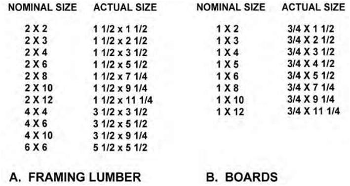
| ample, a finished (dressed) 2 x 4 piece is less than 2 inches thick and less than 4 inches wide. The nominal size is usually greater than the actual dimension. When sawn lumber (nominal size) is seasoned, dressed, or planed, the size becomes smaller; this is the “actual size.” For example, a piece of 2 x 4 lumber (100 x 50) may become approx 11/2 x 31/2 inches (90 x 45) when it has been dressed or planed. The actual size therefore refers to the minimum acceptable size after it has been dressed and seasoned. A nominal 2 x 4 can have a minimum actual size of 1.5 x 3.5 inches. When referring to a specific piece of lumber, the nominal size is used. Figure 4.11 shows examples of nominal and actual sizes of lumber and boards. |
|||
 |
|||
| Figure 4.10 A drawing showing the use of reference dimensions. | |||
| 70 | Chapter 4 | ||
 |
|||
| Figure 4.11 A table showing examples of nominal and actual sizes for framing lumber and boards. | |||
|
In design engineering, size is used for purposes of general identification; the actual size of a part will be approximately the same as the nominal size but need not necessarily be exactly the same. For example, a rod may be referred to as 1/4 inch, although the actual dimension on the drawing is 0.2495 inch; in this case 1/4 inch is the nominal size. |
|||
| 4.7 TOLERANCES | |||
|
The phrase “geometric dimensioning and tolerancing” (GDT) refers to the allowable variation of a dimension. It represents the difference between the maximum and minimum acceptable limits. All dimensions except basic, reference, nominal, maximum, or minimum dimensions must have a tolerance. GDT is a method of specifying the functional geometry of an object. Understanding the international engineering language of GDT is essential for communicating in today’s highly competitive global marketplace. You are required to read and interpret GDT symbols, which provide detailed information about the function and relationship of the various part features. |
|||