
| Drawings and You can also produce drawings and reports for cast units and assemblies. See Cast-unit reports drawing, Assembly drawing, and Printing reports in the Drawing Manual. Assembly hierarchy in nested assemblies affects drawings and reports. You can create separate drawings and reports of the sub-assemblies and the nested assembly, and still produce dimensions, marks, fabrication information, etc. for all assembly levels. |
||||
| Assembly examples | ||||
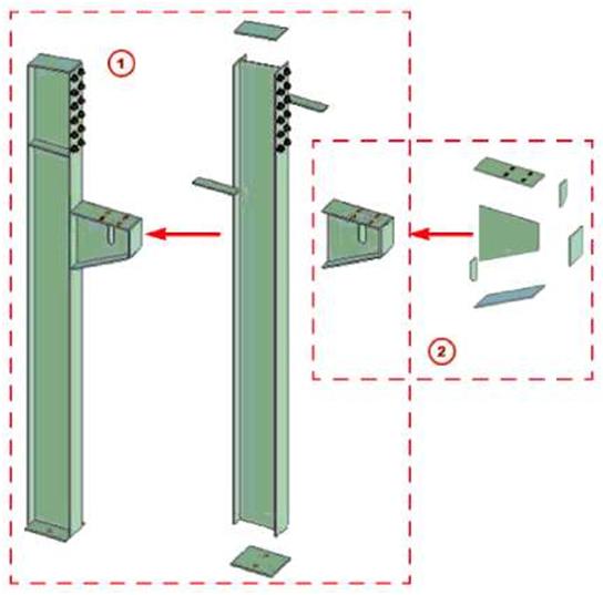
| A column corbel is fabricated in one workshop, and then attached to the column in another workshop. Model the corbel as a sub-assembly of the column. Then create an assembly drawing for each workshop: one assembly drawing showing how the corbel is welded together, another assembly drawing showing how the corbel and the other part are welded to the column. | ||||
 |
||||
| m) Drawing 2, Workshop 2 £2) Drawing 1, Workshop 1 | ||||
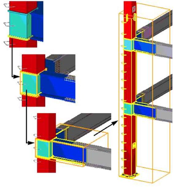
| Model the halves of a complex truss as assemblies. Create assembly drawings for the workshop to fabricate the truss halves. Then create another assembly drawing showing how the halves should be joined on site. In a frame of built-up columns and beams, each built-up profile can be a sub-assembly. You can create an assembly drawing showing the entire frame and separate drawings showing how the columns and beams are built up. |
||||
| 73 | ||||
| Working with assemblies | |||||
| ■s |
To work with nested assemblies, you need to know how to use the Shift key and mouse scrolling to select objects on different levels in assembly hierarchy. |
||||
| You can work on any level of a nested assembly, from single parts and bolts, through the basic and sub-assemblies, up to the highest level of the nested assembly: | |||||
 |
|||||
| 74 | |||||
| T* | You can hide individual assemblies from model views. To do this: 1. Select the assemblies to hide. 2. Right-click and select Assembly > Hide from the pop-up menu. To show the assemblies again in a model view, select the view, right-click, and then select Redraw View from the pop-up menu. To redraw all model views at the same time, click View > Redraw All. |
||||||||||||||||||||||||||||||||
| Adding objects to assemblies You can add objects to assemblies in the following ways: |
|||||||||||||||||||||||||||||||||
|
|||||||||||||||||||||||||||||||||
|
Sub-assemblies in a nested assembly retain their own assembly information and main part. You can also open properties dialog boxes and define properties separately for the sub-assemblies and the nested assembly. To add secondary parts to a basic assembly or to any level of a nested assembly: 1. Ensure that the Select objects in assemblies switch is active. 2. Select the parts to add. 3. Right-click and select Assembly > Add to Assembly from the pop-up menu. 4. Select the assembly to add to. To create nested assemblies: 1. Ensure that the Select assemblies switch is active. 2. Select the assemblies you want to add to another assembly. They will become sub-assemblies in the nested assembly.
|
|||||||||||||||||||||||||||||||||

| 3. Right-click and select Assembly > Add as sub-assembly on the pop-up menu. 4. Select the assembly to add to. To join existing assemblies without adding any loose parts: 1. Ensure that the Select assemblies switch is active. 2. Select the assemblies you want to join. 3. Right-click and select Assembly > Make into Assembly from the pop-up menu. When you use this method to create a nested assembly, by default the assembly with the largest volume will become the main assembly. To change the main assembly, use the Set as New Main Object of Assembly command. Creating sub-assemblies of assembly parts You can create sub-assemblies of parts that are already in an assembly. Usage 1. Ensure that the Select objects in assemblies switch is active. 2. Select the parts you want to include in the sub-assembly. 3. Right-click and select Make into Sub-Assembly from the pop-up menu. Removing objects from assemblies To remove parts from an assembly: 1. Select the part to remove. 2. Right-click and select Assembly > Remove from Assembly on the pop-up menu. To remove sub-assemblies from an assembly: 1. Select the sub-assembly to remove. 2. Right-click and select Assembly > Remove from Assembly on the pop-up menu. To explode an assembly: 1. Select the assembly. 2. Right-click and select Assembly > Explode on the pop-up menu. |
|||
 |
When you explode a nested assembly, Tekla Structures breaks the assembly hierarchy level by level, always starting from the highest level. You need to use the Explode command several times to break a nested assembly back to single parts. | ||
| T | Use the Explode Sub-Assembly command to explode sub-assemblies to single parts without breaking the entire assembly hierarchy. | ||
| Usage | Exploding sub-assemblies You can explode sub-assemblies to single parts without breaking the entire assembly hierarchy. 1. Select the sub-assembly you want to explode. 2. Right-click and select Assembly > Explode Sub-Assembly from the pop-up menu. |
||||||
| Working with cast units | |||||||
| Creating cast units | To create a cast unit: 1. Click Modeling > Cast unit > Create. 2. Select the objects to form the cast unit. 3. Click the middle mouse button to create the cast unit. To add objects to a cast unit: 1. Click Modeling > Cast unit > Add to. 2. Select the object to add. 3. Select an object in the cast unit. |
||||||
| Adding objects | |||||||
| v | You can also add custom components to cast units using the Add to command. | ||||||
 |
To add a custom part to a cast unit: | ||||||
| 1. Ensure that the Select components switch | *Ji | is active. | |||||
| 2. Click Modeling > Assembly > Add as Sub-Assembly. 3. Select the custom part. 4. Select the cast unit. |
|||||||
| Removing objects | To remove objects from a cast unit: 1. Click Modeling > Cast unit > Remove from. 2. Select the object to remove. To explode a cast unit: 1. Click Modeling > Cast unit > Explode. 2. Select an object in the cast unit. When you select cast units for copying, ensure that the Select assemblies switch active. |
is | |||||
| Exploding cast units | |||||||
| Copying cast units See also |
|||||||
| Cast unit type To define whether a concrete part is precast or cast in place: 1. Open the concrete part properties dialog box. 2. Go to the Cast unit tab. |
|||||||
| TEKLA STRUCTURES 14.0 Parts | 77 | ||||||
| 3. In the Cast unit type list box, select Precast or Cast in place. | |||
| T | Tekla Structures checks the cast unit type of the cast unit main part each time you create or modify a cast unit. Tekla Structures does not mix precast and cast-in-place parts inside a cast unit. | ||
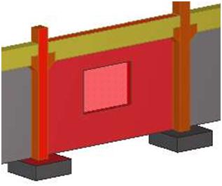
| Defining and showing the top-in-form face To indicate the casting direction of a concrete part, you can define the top-in-form face of the part and show it in model views. The top-in-form face will appear in the front view in drawings. Preconditions Create the concrete part. Usage To define the top-in-form face of a concrete part: 1. Click Modeling > Cast Unit > Set Top in Form Face. 2. Select the part face which will face upwards in the form. To show the top-in-form faces of concrete parts in a model view: 1. Click Modeling > Cast Unit > Show Top in Form Face. 2. Select the parts. Tekla Structures highlights the top-in-form faces in red: |
|||
 |
|||
 |
You can also right-click the part and then select Cast Unit > Set Top in Form Face or Cast Unit > Show Top in Form Face from the pop-up menu. | ||
| To hide the top-in-form faces from a model view, select the view, right-click, and then select Update Window from the pop-up menu. | |||
 |
In drawings, use the Fixed coordinate system to show the top-in-form face in the front view. | ||
| See also Defining concrete part orientation Coordinate system |
|||
| Changing the assembly or cast unit main part | |||
| Use the Inquire commands on the pop-up or pull-down menu to check which is the main part in an assembly or cast unit. To change the main part in an assembly or a cast unit: 1. Click Modeling > Assembly > Set as New Main Object of Assembly. 2. Select the new main part. |
|||
| T* | You can also select the part first and then select Assembly > Set as New Main Part of Assembly from the right-click pop-up menu. | ||
| Changing the main assembly | |||
| You can also change the main assembly in a nested assembly: 1. Click Modeling > Assembly > Set as New Main Object of Assembly. 2. Select the new main assembly. |
|||
 |
You can also select the assembly first and then select Assembly > Set as New Main Sub-Assembly from the right-click pop-up menu. | ||