
| Introduction In Tekla Structures, we use the term parts to refer to the basic components of a model. These are the building blocks of the physical model. For structural analysis purposes, we use the term members to mean load-bearing parts. The main concrete parts are: • beam • polybeam • column • pad footing • strip footing • panel • slab The main steel parts are: • beam • curved beam • orthogonal beam • polybeam • column • twin profile • contour plate |
|||
| In this chapter |
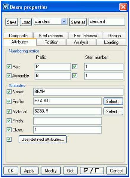
This chapter explains how to create and modify parts using different materials and profiles. It |
||
|
also includes a general description of part properties and an overview of part commands. You can find step-by-step instructions for all these commands in the online help. We assume that you have read Chapter 1, or have comparable knowledge of Tekla Structures. Before you start to create parts, you need to create grids, views, and points, as explained in Chapter 2, This chapter is divided into the following sections: |
|||
| Assumed background Contents |
|||
 |
||||
| fl) Standard profile C2J Parametric profile | ||||
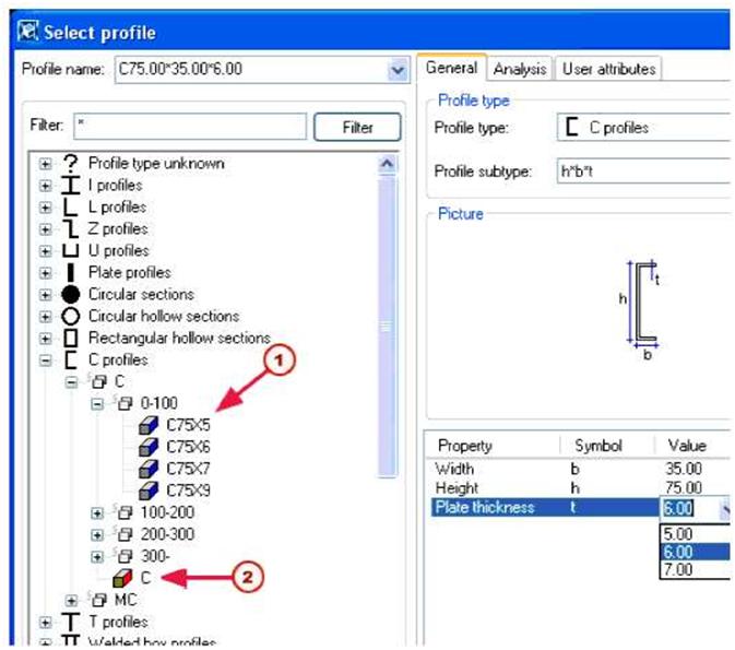
| All profiles and details | You can select a profile from the tree which lists profiles contained in the profile catalog. Profiles are grouped in the tree according to rules (such as profile type) which you can define and modify. Only the profile types that are relevant to the material of the part are shown. For more information on how to modify the profile catalog and rules, and how to associate profile types with materials, see The profile catalog and Working with rules in the online help. If you select a parametric profile, enter the profile dimensions in the Value column. If you select the Show all profiles checkbox, Tekla Structures includes all the profiles in the profile catalog in the tree. To see all the properties of profiles, select the Show details checkbox. For user-defined profiles Tekla Structures also displays cross section information. When you have selected a profile, click Apply or OK. |
|||
| 68 | TEKLA STRUCTURES 14.0 Parts | |||

 |
|||
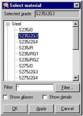
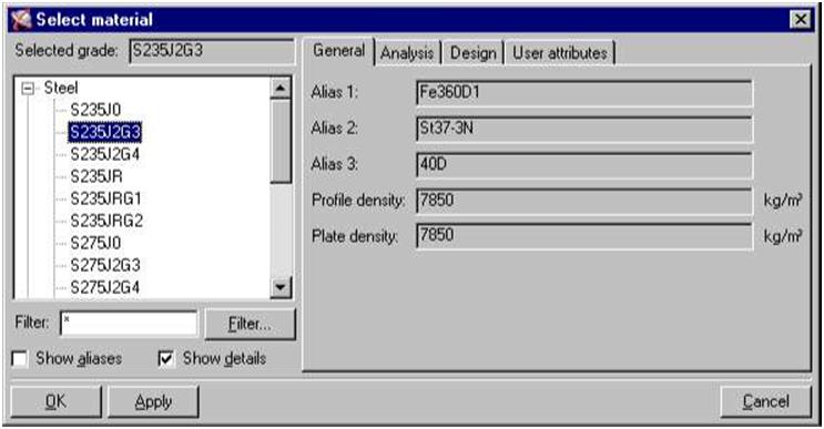
| Aliases and To include aliases for material grades in the tree, in the Select material dialog box, select the details Show aliases checkbox. Aliases are alternative names. For example, they can be former names, or names used in different countries or standards. Tekla Structures automatically translates aliases into the standard name when you select a material grade. To see all the properties of materials, select the Show details checkbox. |
|||
 |
|||
| Analysis The Analysis tab contains information on the properties used in structural analysis, including the modulus of elasticity, Poisson’s ratio, and thermal dilatation coefficient. Design The Design tab contains information on design-specific properties, such as strengths, partial safety factors, etc. User attributes Use the User attributes tab to view or modify the user-defined properties of materials. For example, this tab could contain the maximum grain size, porosity, or surface quality class of a concrete material type, or country-specific properties. When you have selected the material for a part, click Apply or OK. |
|||
| 70 | TEKLA STRUCTURES 14.0 Parts | ||
| T | You can also enter a material name in the Material field in the part properties dialog box. | ||||||||||||||||||||||||||||||||||||||||||||||
| To modify the material catalog, see The material catalog in the online help. User-defined attributes User-defined attributes provide extra information about a part. Attributes can consist of numbers, text, or lists. The following table explains what you can use attributes for: |
|||||||||||||||||||||||||||||||||||||||||||||||
|
|||||||||||||||||||||||||||||||||||||||||||||||
| For more information on defining attributes using the objects.inp file, see Adding properties in the online help. | |||||||||||||||||||||||||||||||||||||||||||||||