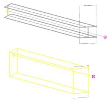
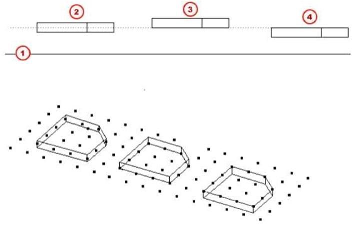
Tekla Structures – Part location

In this section            This section describes the part position properties that vary according to the part type.

Part reference            When you create a part, you position it by picking points. These are the part reference points.

point                            The position of a part is always relative to its reference point(s).

Part reference            If you pick two points to position a part, these points form the part reference line, and handles

line                              appear at the line ends.

When creating horizontal parts, it is worth being consistent and always picking points from left to right, and from bottom to top. This ensures that Tekla Structures places and dimensions the parts in the same way in drawings, and that part marks automatically appear at the same part end.
To see the part reference line in the model:

1.    Click View > View Properties….

2.     Click the Display… button to open the Display dialog box.

3.     On the Advanced tab, select the Part reference line checkbox.

4.     Click Modify and OK. You can use part reference lines to help snapping to the middle points of parts, for example.

Handles Tekla Structures indicates the direction of a part with handles. When you select a part, the handle at the first end is yellow, and the handle at the second end is magenta.
You can use handles to move the part end: 1. Select the part to display the handles.
82 TEKLA STRUCTURES 14.0 Parts


2.    Click the handle you want to move. Tekla Structures highlights the handle.

3.     Move the handle(s) like any other object. If you have Drag and drop on, just drag the handle to a new position.

By default, the handles of contour plates and concrete slabs are not visible. To show them, set the variable XS_DRAW_CHAMFERS_HANDLES to HANDLES.
Position on work plane
Beam You can define the position of a part on the work plane as:

•     Middle

•     Right

•     Left

You can also define the distance of a part from its original reference line.

An example of the options for beams:

(T)    Middle

C2J    Left

L3J    Right

t4j    Middle 200

fSJ    Left 200

MS}    Right 200

TEKLA STRUCTURES 14.0 Parts 83
Position
Beam You can define the position of a part in terms of its depth, perpendicular to the work plane, as:

•      Middle

•      Front

•      Behind An example showing the options for beams:

Contour fl)    Work plane

f2J    Middle

f3J    Front

f4J    Behind

f5j    Middle 100

fej    Front 100

f7J    Behind 100

An example showing the options for contour plates:

(T}    Work plane

f2J    Middle

(3J    Front

f4j    Behind

Rotation
Beam You can define the rotation of a part around its axis on the work plane as:

•     Front

•     Top

•     Back

•     Below

You can also define the angle of rotation. Tekla Structures measures positive values clockwise around the local x axis.

An example of the options for beams:

TEKLA STRUCTURES 14.0 Parts 85
Front
Column ©

f2J   Top

(3J   Back

(4)   Below

fsj    Positive (10 degrees) rotation around local x axis

An example of the options for columns:
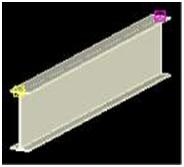
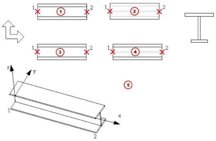
Front
©

f2J   Top

f3J   Back

C4)    Below

Vertical position
You can define the vertical position of a part, relative to its reference point, as:

•     Middle

•     Down

•     Up

Column An example of the options for columns:
Mj    Middle

(2)    Down

f3J    Up

(4J    Middle 100

fsj    Down 100

00   Up 100

Horizontal position
Column You can define the horizontal position of a part, relative to its reference point, as:

•     Middle

•     Left

•      Right An example of the options for columns:

©

Middle

©

Left

©

Right

©

Middle100

©

Left 100

©

Right 100

End offsets

Use end offsets to move the ends of a part, relative to its reference line. You can enter positive and negative values. The options are:

Field Result
Dx Changes the length of the part by moving the part end point along the reference line
Dy Moves the part end perpendicular to the reference line
Dz Moves the part end in the z direction of the work plane
Levels

For parts that you create by picking only one point (e.g. columns), you can enter the positions of the part ends, relative to the picked point, in the global z direction. Use Bottom to define the position of the first end. Use Top to define the position of the second end.

Bending

In Tekla Structures, you create curved parts by defining a radius and the plane of curvature.

Parts
Radius                        When you create a curved part, you pick three points to define the radius. You can also enter a

specific value for the radius in the part properties dialog box.

T The sector angle must be less than 180 degrees.
Plane The plane of curvature is relative to the current work plane. The options are:

•     xz plane

•     xy plane

To have Tekla Structures draw a curved part, you need to specify a number of segments. Tekla Structures does not show curved surfaces exactly in views, instead the number of segments determines how realistic the curved part looks: the more segments, the less angular the part appears. If you specify a large number of segments it affects how quickly Tekla Structures draws the model. See also How handles solids in the online help.

Leave a Comment

This site uses Akismet to reduce spam. Learn how your comment data is processed.