
| framing for increased thermal efficiency The 2 _ 4 (38 _ 89 mm) has been the standard-size wall stud since light framing was invented. In recent years, however, pressures for heating fuel conservation have led to energy code requirements for more thermal insulation than can be inserted in the cavities of a wall framed with members only 3½ inches (89 mm) deep. One solution is to frame walls with 2 _ 6 (38 _ 140 mm) studs, usually at a spacing of 24 inches (610 mm), creating an insulation cavity 5½ inches (140 mm) deep. Alternatively, 2 _ 4-framed walls may be covered either inside or out with insulating plastic foam sheathing, thus reaching an insulation value about the same as that of a conventionally insulated 2 _ 6-framed wall. For even greater insulation performance, 2 _ 6 studs and insulating sheathing may be used in tandem. Alternatively, in very cold climates, even deeper wall assemblies that can achieve greater insulation values may be constructed of two separate layers of wall studs or of vertical truss studs made up of pairs of ordinary studs joined at intervals by plywood plates. |
Usage In wood light frame structures constructed with advanced framing techniques (also called optimum value engineering), special attention is given to minimizing the use of redundant or structurally unnecessary wood members, thereby reducing the amount of lumber required to construct the frame and, once the frame is insulated, increasing its thermal ef ciency A variety of techniques may be used, including: ¥ Spacing framing members at 24 inches (610 mm) rather than 16 inches (406 mm) o.c.: Wider spacing of framing members reduces the amount of lumber required. In exterior walls, thermal ef ciency is also improved by the reduction in thermal bridging area in comparison to walls framed with more closely spaced members. ¥ Designing to a 24-inch (610-mm) module: When the outside dimensions of a framed structure conform to a 24-inch module, sheathing panel waste is minimized. Planning rough opening sizes and locations in ß oors, walls, and roofs to conform, where possible, to modular dimensions can reduce waste even further. Designing to modular dimensions also reduces wastage of interior wallboard. ¥ Using single top plates in all walls, both bearing and nonbearing: In the case of bearing walls, this requires ß oor or roof framing members to align directly over studs in the walls that support them. ¥ Minimizing other unneeded framing members: DonÕt use headers over openings in nonbearing walls, since they are not needed; in bearing walls, use headers only as deep as required for the loads and span. Where corner studs serve only to provide nailing surfaces or support for wallboard, use other, less wasteful blocking techniques or metal clips designed for this purpose instead. Replace jack studs supporting headers at window and door openings with metal hangers; eliminate unneeded cripple studs under rough sills. All of these techniques save lumber and, in exterior walls, increase energy ef ciency by reducing thermal bridging through solid framing members. ¥ Eliminating unneeded plywood and OSB wall sheathing: Where letin bracing is structurally adequate for lateral force resistance, eliminate structural panel wall sheathing entirely and cover walls with insulating sheathing for better thermal ef – ciency. Where structural panels are required, use the minimum extent of panels necessary. Advanced framing techniques rely on unconventional framing methods and signi cantly reduce redundancy in the building frame. For these reasons, they should not be used without guidance from a structural engineer or other quali ed design professional, and special review and approval from local building authorities may be required. Nevertheless, where these techniques are used, signi cant bene ts can be realized. According to the National Association of Home Builders Partnership for Advancing Technology in Housing, advanced framing techniques can reduce the amount of lumber used in a wood light frame structure by up to 19 percent and improve the energy ef ciency of the insulated structure by as much as 30 percent.
|
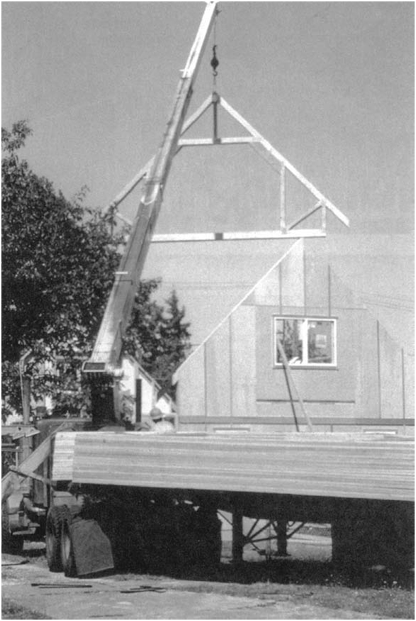
Figure 5.65
Roof trusses are typically lifted to the roof by a
boom mounted on the delivery truck. This is one
of a series of identical attic trusses, which will
frame a habitable space under the roof. (Photo by Rob Thallon)
prefabricated framing assemblies
Roof trusses, and to a lesser extent fl oor trusses, are used in platform frame buildings because of their speed of erection, economy of material usage,
and long spans. Though many ß oor trusses are light enough to be lifted and installed by two carpenters, most truss assemblies are erected with the
aid of a small crane that often is attached to the truck on which the trusses are delivered (Figure 5.65). Roof trusses are particularly slender
in proportion, usually only 1½ inches (38 mm) thick and capable of spanning 24 to 32 feet (7.5 to 10 m). They must be temporarily braced during
construction to prevent buckling or the dominolike collapse of all the trusses until they are adequately secured permanently by the application
of roof sheathing panels and interior nishes (Figure 5.66). Manufactured wall panels have been adopted more slowly than roof
and ß oor trusses, and are used mostly by large builders who build hundreds or thousands of houses per year. For the smaller builder, wall framing can
be done on site with the same amount of material as with panels and with
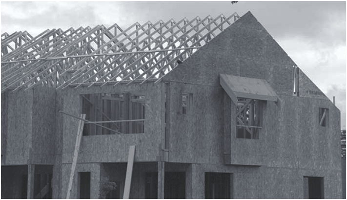
Figure 5.66 A roof framed with prefabricated trusses. Approximately midway up the upper chords of the trusses, temporary strapping ties the trusses to one another for bracing. Other diagonal bracing, not visible in this photograph, ties the trusses to floor or ceiling framing to prevent the entire row from collectively tipping sideways. (Photo by Joseph Iano)