| 7.1 GENERAL | |||
|
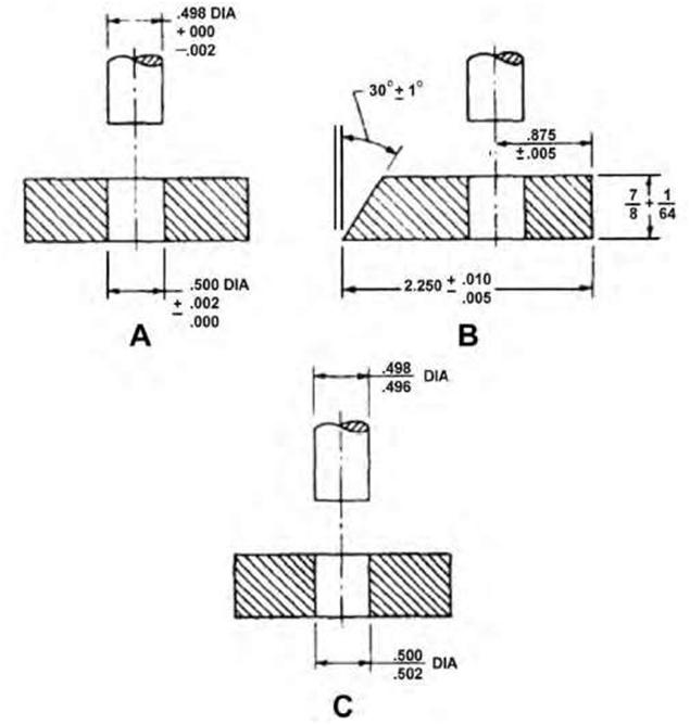
Industrial drawings may often necessitate more description and detail than some other types of working drawings, mainly because of the close tolerances and finished surface requirements. In this chapter we will cover some of the more common terms and symbols that the blueprint reader must be familiar with in order to read machine drawings. Some of the basic mechanisms usually found in detail and assembly drawings of machines are also presented. One of the first steps in learning to read machine drawings is to become familiar with key terms, symbols, and conventions in general use in the industry. Although today’s CAD packages make the production of industrial drawings much easier, it is still imperative to follow industry standards and conventions. Tolerance Tolerance represents the total amount a dimension may vary. It is basically defined as the difference between the upper and lower limits. Working to absolute or exact basic dimensions is impractical and unnecessary in most instances; therefore, the designer calculates in addition to the basic dimensions an allowable variation. Work must therefore be implemented within the limits of accuracy specified on the drawing. A clear understanding of tolerance and allowance can go a long way toward preventing small but potentially critical errors. Tolerance is shown on a drawing as ± (plus or minus) a certain amount, either as a fraction or decimal. Limits are the maximum and/or minimum values prescribed for a specific dimension, while tolerance represents the total amount by which a specific dimension may vary. Tolerances may be shown on drawings in a number of different ways. Figure 7.1 shows three examples: A. The unilateral method, which is used when variation from the design size is permissible in one direction only; B. The bilateral method, where the dimension figure shows the variation in either direction that is acceptable; and C. The limit-dimensioning method, where the maximum and minimum measurements are both stated. Figure |
|||
| Copyright © 2009 by The McGraw-Hill Companies, Inc. Click here for terms of use. | 163 | ||
| 164 | Chapter 7 | ||
 |
|||
| Figure 7.1 Three methods of indicating tolerances: A. Unilateral method, B. Bilateral method, and C. Limit dimensioning method (source: Blueprint Reading and Sketching, Navedtra 14040). | |||
|
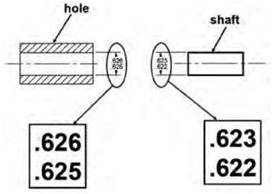
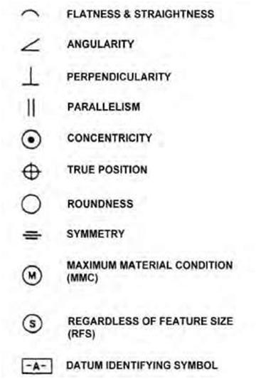
7.2 illustrates a typical method used to show tolerances for holes and shafts. Surfaces being toleranced have geometrical characteristics such as roundness or perpendicularity to another surface. Figure 7.3 demonstrates typical symbols used in lieu of or in conjunction with notes to state the geometric characteristics being toleranced. |
|||
| Understanding Industrial Blueprints | 165 | ||
|
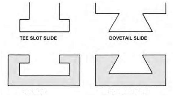
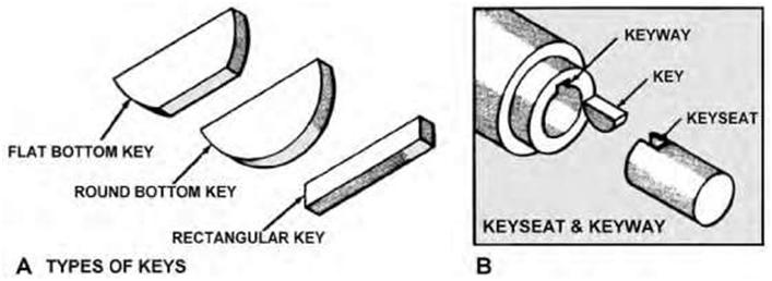
If tolerances are not actually specified on a drawing, certain assumptions can be made regarding the anticipated accuracy by applying the following principles: For dimensions ending in a fraction of an inch, such as 1/8, 1/16, 1/32, or 1/64, the required accuracy will be to the nearest 1/64 inch. When the dimension is given in decimal form, the following principles should be followed: If a dimension is given as 2.000 inches, the accuracy expected is ±0.005 inch; if the dimension is given as 2.00 inches, the accuracy expected is ±0.010 inch. The ±0.005 is called in shop terms “plus or minus five thousandths of an inch.” The ±0.010 is called “plus or minus ten thousandths of an inch.” Fillets and Rounds Fillets are concave metal corner (inside) surfaces. In a cast, a fillet normally increases the strength of a metal corner because a rounded corner cools more evenly than a sharp corner, thereby reducing the possibility of a break. Rounds or radii are edges or outside corners that have been rounded to prevent chipping and to avoid sharp cutting edges. Figure 7.4 shows an example of fillets and rounds. Slots and Slides Slots and slides are used to mate two specifically shaped pieces of material and securely hold them together, while allowing them to move or slide. Figure 7.5 shows two common types: the tee slot and the dovetail slot. A tee-slot arrangement is usually used on a milling-machine table, while a dovetail slot is often used on the cross-slide assembly of an engine lathe. Keys, Keyseats, and Keyways These terms denote several types of small wedgelike metal objects designed to fit mating slots in a shaft and the hub of a gear or pulley to prevent slippage and provide a positive drive between them. Parts can be keyed together by means of a flat piece of steel that is partly seated in a recessed shaft or groove called a keyseat. Figure 7.6 shows three types of keys, a keyseat, and a keyway. A keyseat is a slot or groove on the outside of a part into which the key fits. A keyway is a slot or groove within a cylinder, tube, or pipe. A key fitted into a keyseat will slide into the keyway and prevent movement of the parts. Drawings usually include a height dimension that states the measurement from the circumference to the depth to which the keyway and keyseat are machined. Coordinate Measuring Machines Coordinate measuring machines (CMM) use software and sensors to compare computer prototype drawings to the finished prototype. Tool and die makers must use accurate prototypes to tool a production line that will produce identical quality components. Casting It is the production of metal components by pouring molten metal into moulds and allowing it to solidify. It can also be a metal component produced by casting. |
|||
| 166 | Chapter 7 | ||
 |
|||
| Figure 7.2 A typical method used to show tolerances for holes and shafts (source: College of Engineering, Ohio State University). | |||
 |
|||
| Figure 7.3 Examples of geometric symbols used in industrial drawings. | |||
| Understanding Industrial Blueprints | 167 | ||
 |
|||
| Figure 7.4 Fillets and rounds. | |||
 |
|||
| TEE SLOT DOVETAIL SLOT Figure 7.5 Examples of slot and slide arrangements. |
|||
 |
|||
| Figure 7.6 Diagram showing three types of keys, a keyseat and a keyway (source: Blueprint Reading and Sketching, Navedtra 14040). | |||
| 168 | Chapter 7 | ||
| Forging Forging is a process of shaping metal while it is hot and pliable by suitably applying compressive force. Usually the compressive force takes the form of hammer blows using a power hammer or a press. To achieve good forgings, a proper lubricant is necessary. The lubricant helps prevent the work piece sticking to the die and also acts as a thermal insulator to help reduce die wear. Forging refines the grain structure and improves the physical properties of the metal. With proper design, the grain flow can be oriented in the direction of principal stresses that are encountered in actual use. Grain flow is the direction of the pattern that the crystals take during plastic deformation. Physical properties (such as strength, ductility, and toughness) are much better in a forging than in the base metal, whose crystals are randomly oriented. Forgings yield parts that have a high strength-to-weight ratio. Common forging processes include: Open-die or hand forgings are a traditional and antiquated manufacturing process based on repeated blows in an open die, where the operator manipulates the work piece in the die. The finished product is a rough approximation of the die. Press forging is the shaping of metal between dies on a mechanical or hydraulic press. The action is that of kneading the metal by relatively slow application of force as compared with the action of hammering. This results in uniform material properties and is necessary for large weight forgings. Parts made with this process can be quite large as much as 125 kg (260 lb) and 3m (10 feet) long. Impression-die forgings or precision forgings are further refinements of blocker forgings (blocker forging is a forging that approximates the general shape of the final part with relatively generous finish allowance and radii. Such forgings are sometimes specified to reduce die costs where only a small number of forgings are desired and the cost of machining each part to its final shape is not exorbitant). Finished components more closely resemble the die impression. Upset forgings increase the cross section by compressing the length and are used in making heads on bolts and fasteners, valves, and other similar parts. In roll forging (also known as draw forging) a round or flat bar stock is placed between die rollers, which reduces the cross section and increases the length to form parts such as axles, leaf springs etc. Draw forging also involves pulling a hollow tube through a series of hardened steel dies of gradually decreasing diameter. Before each step of the drawing process, the tube is pointed at one end to fit through the next smaller die and is then gripped by automatic jaws attached to a rotating drawing machine. In swaging a tube or rod is forced inside a die and the diameter is reduced as the cylindrical object is fed. The die hammers the diameter and causes the metal to flow inward, causing the outer diameter of the tube or the rod to take the shape of the die. Net and near net shape forging represents a number of recent developments of the conventional impression die forging process. Net and near net shape forgings are distinguished by geometric features that are thinner and more detailed, varying parting line locations, virtual elimination of draft, and closer dimensional tolerances. The resulting product benefits are much fewer machining operations (in many cases, the only machining operations required are drilling of attachment holes), reduced weight and lower costs for raw materials and energy. The processes are quite costly in terms of tooling and the capital expenditure required. Thus, these processes can only be justified for current processes that are very wasteful where the material savings will pay for the significant increase in tooling costs. |
|||
| Understanding Industrial Blueprints | 169 | ||
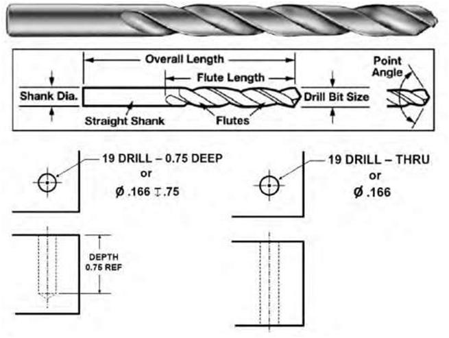
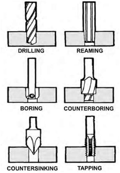
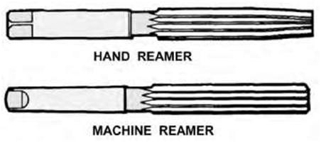
| Die A die is a tool used to form or stamp out metal parts or to cut external threads. Dies can be simple objects or made of a series of jigs and fixtures to ensure that the die makes contact with the metal stock at the correct place and angle. Tempering Tempering is a process of heat treatment to change the physical characteristics of ferrous alloys. The object of tempering or drawing is to reduce the brittleness in hardened steel and to remove the internal strains caused by the sudden cooling in the quenching bath. The tempering process consists of heating the steel by various means to a certain temperature and then cooling it. The rate of cooling usually has no effect on the metal structure during tempering. Therefore, the metal is usually allowed to cool in still air. When steel is in a fully hardened condition, its structure consists largely of martensite. On reheating the steel to a temperature of about 300 to 750 degrees F, a softer and tougher structure known as troos-tite is formed. If the steel is reheated to a temperature of 750 to 1290 degrees F, a structure known as a sorbite is formed, which, while lacking the strength of troostite, has far greater ductility. High-speed steel is one of the few metals that will become harder instead of softer after it is tempered. Drill A drill is a pointed tool that is rotated to cut holes in material. Figure 7.7A shows a typical drill with its related nomenclature and two holes,one 0.75 deep and the other through, as well as the operations of upright drilling machines. Boring To bore is to enlarge and finish the surface of a cylindrical hole by the action of a rotating boring bar (cutting tool) or by the action of a stationary tool pressed (fed) against the surface as the part is rotated. Boring produces a hole with a continuous inside diameter or a tapered or contoured diameter. When a straight and smooth hole is required that is too large or odd-sized for drills or reamers, a boring tool can be utilized to bore any size hole into which the tool holder will fit by inserting it into the drilling machine. A boring bar with a tool bit installed is used for boring on larger drilling machines. To bore accurately, the setup must be rigid, the machine sturdy, and a power feed used. Reaming Reaming consists of enlarging a hole. It is similar to boring but is more precise and is implemented after boring or drilling. Reaming is performed with a drill machine or lathe; it is difficult if not impossible,to drill a hole to an exact standard diameter. Where extra accuracy is specified, the holes should first be drilled slightly undersized and then reamed to size. The majority of hand and machine reamers have a slight chamfer at the tip to aid in alignment and starting (Figure 7.8). Tapping Tapping is the process of cutting a thread in a drilled hole and cutting internal threads. Tapping can be accomplished on a lathe or drilling machine. On a drilling machine it is done by selecting and drilling the |
|||
| 170 | Chapter 7 | ||
 |
|||
| Figure 7.7A A typical drill with the terminology related to it and two holes—one 0.75 deep and the other through. | |||
|
tap drill size, then using the drilling-machine chuck to hold and align the tap while it is turned by hand. There are typically three types of taps used: a tapered tap to facilitate initial thread cutting; an intermediate type, used to progress the thread after it has been started; and a “bottoming” thread, which is used to obtain the full thread depth when cutting partway through the piece. |
|||
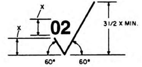
| Finish Marks Many metal surfaces must be finished with machine tools for various reasons. The acceptable roughness of a surface depends upon how the part will be used. Sometimes only certain surfaces of a part need to be finished while others are not. A modified symbol (check mark) with a number or numbers above it is used to show these surfaces and to specify the degree of finish required. The proportions of the surface roughness symbol are shown in Figure 7.9. On small drawings the symbol is proportionately smaller. |
|||
| Understanding Industrial Blueprints 171 | ||
 |
||
| Figure 7.7B Operations of the upright drilling machine. | ||
|
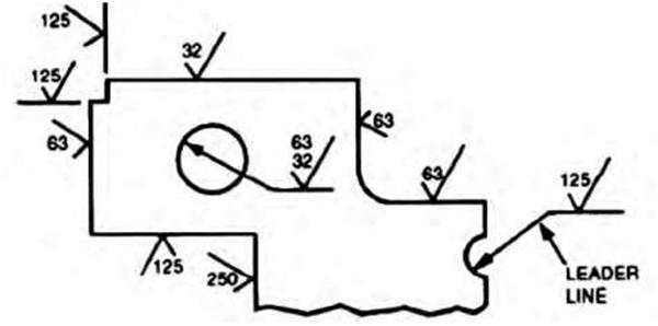
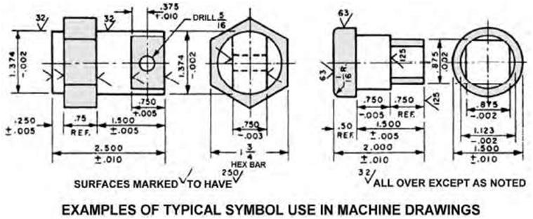
The number in the angle of the check mark, in this case “02,” tells the machinist the degree of finish the surface should have. This number is the root-mean-square value of the surface roughness height in millionths of an inch. In other words, it is a measurement of the depth of the scratches made by the machining or abrading process. Wherever possible, the surface roughness symbol is drawn touching the line representing the surface to which it refers. If space is limited, the symbol may be placed on an extension line on that surface or on the tail of a leader with an arrow touching that surface, as shown in Figure 7.9. When a part is to be finished to the same roughness all over, a note on the drawing will include the direction “finish all over” along the finish mark and the proper number. When a part is to be finished all over but a few surfaces vary in roughness, the surface roughness symbol number or numbers are applied to the lines representing these surfaces, and a note on the drawing will include the surface roughness symbol for the rest of the surfaces. |
||
| 172 | Chapter 7 | ||
 |
|||
| Figure 7.8 A hand reamer and a machine reamer. Solid hand reamers are typically used when a greater accuracy in hole size is desired. Machine reamers can generally be expected to produce clean holes when used properly. | |||
 |
|||
| Figure 7.9A The proportions of the surface roughness symbol. | |||
 |
|||
| Figure 7.9B The method of placing surface roughness symbols. | |||
| Understanding Industrial Blueprints | 173 | ||
 |
|||
| Figure 7.9C Examples of finish marks on a drawing. | |||
| 7.2 INDUSTRIAL DRAWINGS | |||
|
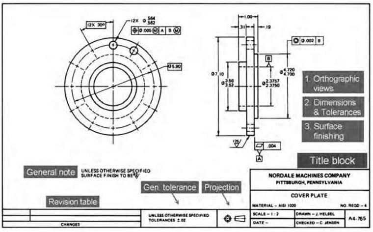
A working drawing is a drawing that includes all the information required to successfully and accurately execute a job. A detail drawing is essentially a working drawing that incorporates much more specific information including the size and shape of the project, the materials to be used, finishing information, and degree of accuracy needed. An assembly drawing, on the other hand, may incorporate very little detail (Figure 7.10). The purpose of this type of technical drawing is mainly to show how the machine is to be assembled. There are several types of detail drawings used in various industrial settings. They convey the information and instructions for manufacturing the part, including the object’s shape, size, and specifications. The detail drawing should provide all the information needed to produce the particular part (Figure 7.11). In addition to the part production, the detail drawing can be used when bidding a job or as a master drawing from which other drawings are produced. The information on a detail drawing is specific to the part to be produced, typically drawn one part per page or sheet. Included in the information should be the pertinent shape, size, specifications, and notes. The notes and/or title-block information would normally include the scale, tolerances, surface texture, and specified material. Other data may be required that stipulate finish specification, moisture contents, color code, and other specifications requested by the customer. |
|||
| 174 | Chapter 7 | |||||||
| Industrial drawing | ||||||||
 |
||||||||
| Detail drawing | ||||||||
| Assembly drawing | ||||||||
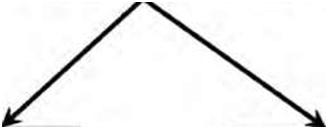
| Figure 7.10 Two categories of industrial drawings are detail drawings and assembly drawings. | ||||||||
 |
||||||||
| Figure 7.11 A detail drawing showing some of the items that need to be included such as orthographic views, dimensions and tolerances, surface finishes, general notes, revision table, and title block. | ||||||||
| Understanding Industrial Blueprints | 175 | ||
|
A casting drawing details the size and location of separation lines, called parting lines. When the mold separates, the parting line is left on the casting. The other information typically found on a casting detail drawing may be a pattern number, sand requirements, part numbers, customer name, draft, shrinkage, finish, ribs and other support webbing, and the material used in the casting/mold. Wood patterns, made by patternmakers in the general male or female shape of the finished part are configured into the sand mold and removed, leaving an impression to be filled with molten metal. When cooled, this metal casting is removed and the process is continued. These castings are then machined into items such as engine blocks, cast-iron tools, or other metal castings we use every day. Bearing blocks, machinery bases and parts, and many household items have castings produced in this manner. 7.3 MACHINIST DRAWINGS |
|||
|
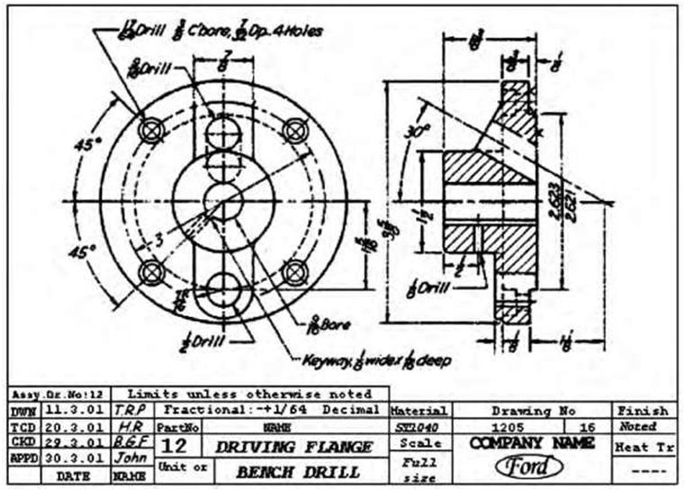
Machinists generally use precision machine tools such as lathes, boring machines, milling machines, and cylindrical or surface grinders to shape materials such as steel, brass, iron, bronze, aluminum, titanium, and plastics and to manufacture components to meet customers’ specifications. A machining detail drawing provides all the information needed to manufacture a specific part and is used to machine the casting into a finished component. Typically only one part is detailed in each drawing. Machining details are generally used when machining a rough part into a finished part; a machining detail drawing will specify the surfaces to be machined, bolt holes and locations, reference points, geometric dimensioning and tolerancing (GD & T), and other machined areas. Machining drawings contain critical information to the traditional or CNC (computer numerically controlled) machinist, which would include angles, reference points, surface finish, etc. Once complete, this machined part should match and fit other machined parts as defined in an assembly/detail drawing. Parts that would not normally need to be drawn are standard parts—those that may be purchased from an external source more economically than it would cost to manufacture. Such parts may include screws, nuts, bolts, keys, and pins. While they do not need to be drawn, they nevertheless need to be included as part of the information on each sheet. The blueprint reader must clearly understand the shape, size, material, and surface finish of a part, which shop operations are necessary, and the limits of accuracy that must be observed from the detail drawing. Figure 7.12 is an example of a typical detail drawing. Normally, detail drawings contain information that is classifiable into three groups: 1. Shape description: describes and explains or portrays the shape of the component 2. Size depiction: shows the size and location of features of the component 3. Specifications: relates to such items as material and finish Detail machine drawings should include all or most of the following information: Views of the component as necessary to allow visualization Material used to manufacture the component Dimensions General notes and specific manufacturing information Identification of the project name, the part, and the part number Name or initials of who worked on or with the drawing Any engineering changes and related information |
|||
| 176 | Chapter 7 | ||
 |
|||
| Figure 7.12 A typical machine detail drawing (source: Middle East Technical University). | |||
|
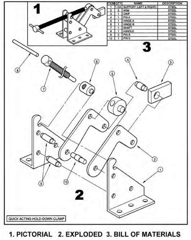
A complete assembly drawing is a presentation of the product or structure put together, showing the various components in their operational positions. The separate components come to the assembly department after their manufacturing processes are finished, and here they are put together according to the assembly drawings. Many products consist of more than one part or component. A bill of materials (BOM) or list of component parts is often included on an assembly drawing to facilitate the assembly, as well as necessary dimensions and component labeling (Figure 7.13). A three-dimensional picture of a complete assembled unit would help the reader to understand the final shape of the assembly. Front, side, and top views may be critical to communicate dimensions or shapes to the reader. If the assembly drawing is actually one of several subassemblies, the print should indicate this in the title block or bill of materials. Movements of components in an assembly detail drawing should be indicated with the use of phantom lines. |
|||
| Understanding Industrial Blueprints | 177 | ||
 |
|||
| Figure 7.13 A sectioned assembly drawing with a bill-of-materials table (source: College of Engineering, Ohio State University). | |||
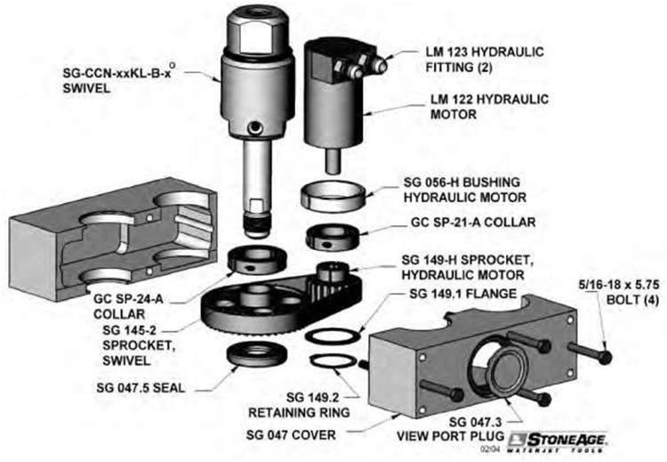
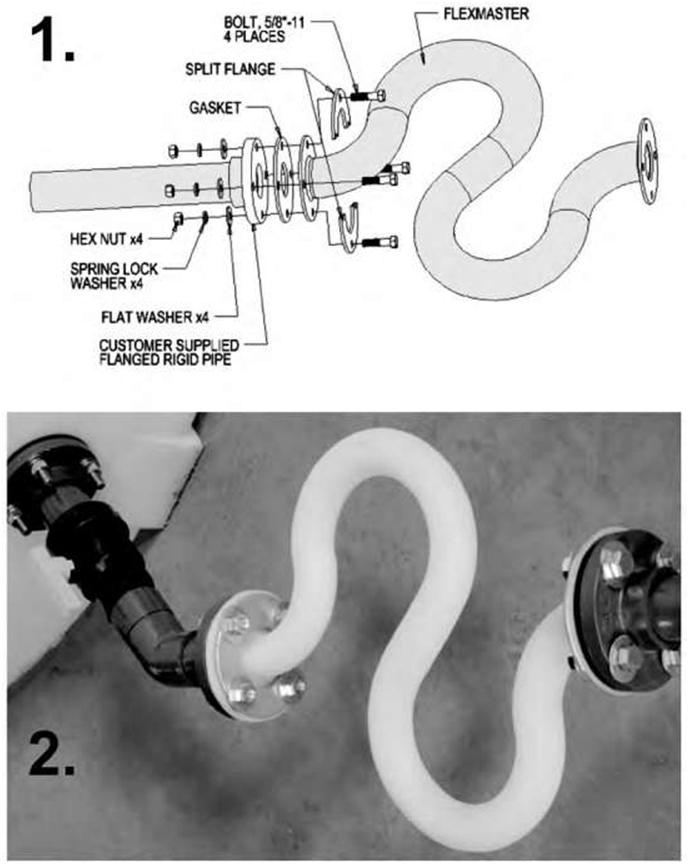
| There are various types and versions of assembly drawings including: Layout assembly drawings initially used in development of a new product. Exploded assembly drawings pictorially showing parts laid out in their correct order of assembly, found in machinery catalogs designed for homeowners or suppliers for ordering parts (Figure 7.14). Diagram assembly drawings use conventional symbols and are used to show the approximate location and/or sequence of the components to be assembled or disassembled. Working assembly drawings are fully dimensioned and noted. When applied to very simple products, they can act as alternatives to detail drawings. Installation assembly drawings are used to show how to install large components of equipment. As mentioned earlier, an assembly drawing is a drawing of various parts of a machine or structure in their relative working positions. An assembly drawing essentially conveys the completed shape of the product as well as its overall dimensions, relative position of the different parts, and the functional relationship of its components. When all the parts are produced using their respective machining detail draw- |
|||
| 178 | Chapter 7 | ||
 |
|||
| Figure 7.14A An exploded assembly drawing typical of drawings found in machinery catalogs showing the various components laid out in their correct order of assembly (source: StoneAge, Inc.). | |||
|
ings, an assembly drawing provides the information the print reader needs to assemble the components. The bill of materials (BOM), which is basically a tabulated list, may be placed either on the assembly drawing or on a separate sheet. The list gives critical information such as part numbers, names, quantities, material detail-drawing number, and sometimes stock sizes of raw material, etc. The term “bill of materials” is usually used in structural and architectural drawing, whereas the term “part list” is used in machine-drawing practice. A three-dimensional picture of a complete assembled unit facilitates the reader’s ability to visualize the final shape of the assembly (Figure 7.15). Front, side, and top views may be necessary to communicate dimensions or shapes to the reader. If this assembly drawing is actually one of several subassem-bly drawings, the print should indicate this in the title block or the BOM. Likewise, a maintenance technician would normally need assembly drawings at the work site to evaluate the best sequence for the dismantling of specific machinery, to locate parts that must be ac- |
|||
| Understanding Industrial Blueprints | 179 | ||
 |
|||
| Figure 7.14B An exploded assembly drawing and photograph of a Flexmaster expansion joint (source: Snyder Industries, Inc.). | |||
| 180 | Chapter 7 | ||
|
cessed or attachment bolts of those to be removed, and to provide detail information on components disassembled for repair. Finally, the technician needs to accurately discern the correct alignment of components upon reassembly. Customers who deal with consumer products such as electronic goods will also normally require the use of exploded CAD drawings to help in understanding the relationships among assembled parts. Exploded drawings are indispensable for a number of manufacturing industries. While generating assembly drawings, critical interference checks are included to ensure that the entire assembly is integrated, thus saving a tremendous amount of time and costs in the prototyping phase. Computer-aided drafting has proved to be a huge timesaver when an assembly drawing is being produced. Today, there are a large number of sophisticated CAD programs and equipments, and the vast majority of manufacturers now use these programs to recover high initial production costs. Although many assembly drawings do not require dimensions, overall dimensions and distances between the centers or from part to part of the different pieces to clarify the relationship of the parts with each other can be included. Most important, however, an assembly drawing should be easy to read and not be overloaded with detail. Utilizing CAD programs likewise allows individual component details to be merged together to create an assembly or working drawing of the component(s). With CAD systems, three-dimensional (3-D) models can be created that makes it possible to superimpose images and to graphically measure clearances. When parts have been designed or drawn incorrectly, the errors will often stand out so that appropriate correction can be made. This improves the efficiency of the drafter and helps to make the details in the final print accurate and the resultant parts function properly. Information normally required for general assembly drawings includes: Parts to be drawn in their operating position Part list (or bill of materials) including item number, descriptive name, material, and quantity required per unit of machine Leader lines with balloons drawn around part numbers Machining and assembly operations and critical dimensions related to the operation of the machine Steps in creating an assembly drawing include the following: 1. Analyze the geometry and dimensions of the various parts in order to understand the assembly steps and overall shape of the object. 2. Select an appropriate view of the object. 3. Choose the major components—components that require assembly of several parts . 4. Draw a view of the major components according to a selected viewing direction. 5. Add detail views of the remaining components at their working positions. 6. Add balloons, notes, and dimensions as required. 7. Create a bill of materials (BOM). Assembly drawings can require one, two, three, or more views, although they should be kept to the minimum necessary. A good viewing direction should be chosen that represents all (or most) of the parts assembled in their working position. |
|||
| Understanding Industrial Blueprints | 181 | ||
 |
|||
| Figure 7.15 Diagram showing how multiple parts fit together and a bill of material and pictorial view of the assembled object (source: College of Engineering, The Ohio State University). | |||
| 182 | Chapter 7 | ||
|
In mating parts the two main considerations are the surface finishing and the tolerance (especially size and geometry). The surface finishing means the level of roughness of a surface. Its main purpose is to control the accuracy in positioning and tightness between the mating parts. The other objective is to reduce the friction, especially for parts that move relative to other parts. 7.4 SCREW THREADS, GEARS, AND HELICAL SPRINGS |
|||
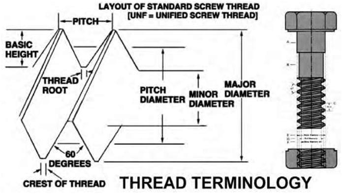
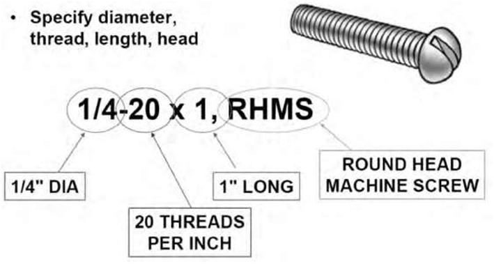
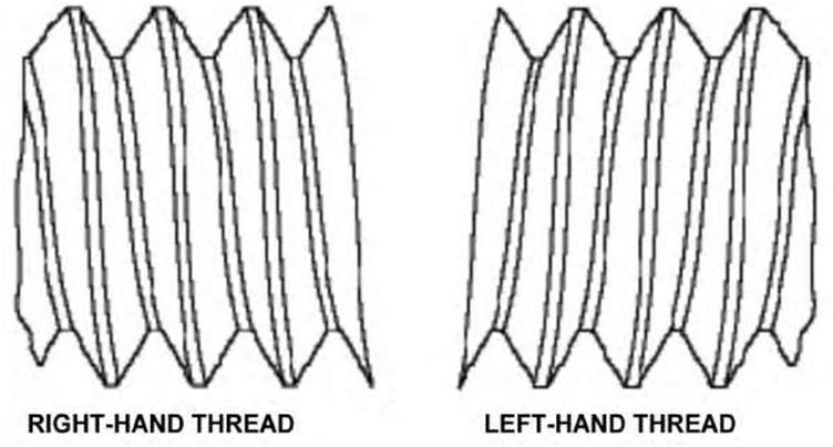
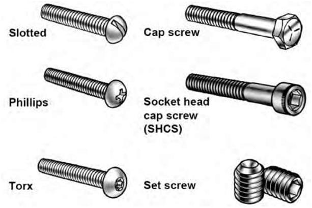
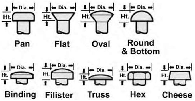
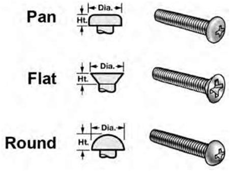
| Threads Machine screws are extensively used for securing parts. There are many different types and sizes of machine screws, nuts, and bolts. Moreover, drafters use different methods to show thread on drawings. Figure 7.16 shows a thread profile in section and a common method of drawing threads. To save time, the drafter uses symbols that are not drawn to scale. The drawing shows the dimensions of the threaded part, but other information may be placed in “notes” almost anywhere on the drawing but most often in the upper left corner. Figure 7.17 gives an example of a typical note showing the thread designator “1/4-20×1, RHMS.” The first number of the note, 1/4, is the nominal size, which is the outside diameter. The number after the first dash, 20, means that there are 20 threads per inch. The number 1 represents the length of the screw, and the letters RHMS identify the head type (round-head machine screw). It would normally also have letters identifying the thread series (e.g., UNC if it were a unified national coarse thread) and a number to identify the class of thread (e.g., “3”) and tolerance, commonly called the fit. If it is a left-hand thread, a dash and the letters LH will follow the class of thread. Threads without the LH designation are right-hand threads. Figure 7.18 shows right-hand and left-hand screws. Figure 7.19 is another example of a screw type and the general nomenclature used to describe it. Specifications necessary for the manufacture of screws include thread diameter, number of threads per inch, thread series, and class of thread. The two most widely used screw-thread series are unified or national form threads, which are called national coarse or NC, and national fine, or NF, threads. NF threads have more threads per inch of screw length. Common NC Screw-Thread Sizes o2-56 o1/4-20 o4-40 o3/8-16 o6-32 o1/2-13 o8-32 o5/8-11 o10-24 o3/4-10 Diameter = (N*.013) + .060 (inches) Classes of threads are distinguished from each other by the amount of tolerance and/or allowance specified. Classes of thread were formerly known as class of fit, a term that will probably remain in use for many years. External threads or bolts are designated with the suffix “A,” internal or nut threads with the suffix “B.” Figure 7.19 shows different types of screws and screw heads. The unified and American (national) thread forms designate classifications for fit to ensure that mated threaded parts fit to the tolerances specified. The unified-screw-thread form has specified a number of classes of threads: |
|||
| Understanding Industrial Blueprints | 183 | ||
 |
|||
| Figure 7.16 A typical screw thread with profile section and the terminology associated with its use in today’s industry. | |||
 |
|||
| Figure 7.17 A typical note showing the thread designator “1/4-20×1, RHMS.” It specifies the diameter, thread, length, and head. | |||
| 184 | Chapter 7 | ||
 |
|||
| Figure 7.18 Right- and left-handed thread screw types. | |||
|
Class 1A and 1B: for work of rough commercial quality where loose fit, quick assembly, and rapid production are important and shake or play is not objectionable. Class 2A and 2B: the recognized standard for normal production of the great bulk of commercial bolts, nuts, and screws. Classes 2A and 2B provide a small amount of play to prevent galling and seizure in assembly and use and sufficient clearance for some plating. Class 3A and 3B: these have no allowance and 75 percent of the tolerance of Classes 2A and 2B. A screw and nut in this class may vary from a fit having no play to one with a small amount of play. This fit represents an exceptionally high quality of commercially threaded product and is recommended only in cases where the high cost of precision tools and continual checking are warranted. Class 4: this is a theoretical rather than practical class and is now obsolete. Class 5: for a wrench fit, used principally for studs and their mating tapped holes or a force fit requiring the application of a high torque for semipermanent assembly. It is also a selective fit if initial assembly by hand is required. It is not as yet adaptable to quantity production. |
|||
| Understanding Industrial Blueprints | 185 | ||
 |
|||
| Figure 7.19A Different types of screws and screw heads. | |||
 |
|||
| Figure 7.19B Different types of screws and screw heads. | |||
| 186 | Chapter 7 | ||
 |
|||
| Figure 7.19C Different types of screws and screw heads. | |||
 |
|||
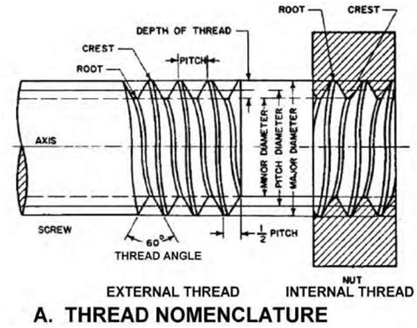
| Figure 7.20 A typical screw thread with the terminology and nomenclature associated with its use in today’s industry. | |||
| Understanding Industrial Blueprints | 187 | ||
| Handedness Almost all threaded fasteners tighten when the head or nut is rotated clockwise. That is, as a viewer turns a nut clockwise it moves away from her. Such a fastener is said to have a right-hand thread; all screw fasteners are assumed to be right-hand unless otherwise specified. Left-hand threads are usually found only on rotating machinery. For example, the axles of bicycle pedals screw into threaded holes in the cranks. In a pair of pedals one will have a right-hand thread and the other a left-hand thread. That way the rotation of the pedals doesn’t tend to unscrew their axles. To designate a left-hand thread, the letters “LH” are placed after the class of fit: 3/8-16 UNC 2B LH (21). Helix A helix denotes the curve formed on any cylinder by a straight line in a plane that is wrapped around the cylinder with a forward progression. Common objects formed like a helix are a spring, a screw, and a spiral staircase. Helices can be either right-handed or left-handed. With the line of sight being the helical axis, if clockwise movement of the helix corresponds to axial movement away from the observer, then it is a right-handed helix. If counterclockwise movement corresponds to axial movement away from the observer, it is a left-handed helix. External Thread An external thread, also known as a male thread, is a thread on the outside of a cylinder or cone. An example is the thread of a bolt. Internal Thread Also known as a female thread, an internal thread is a thread on the inside of a hollow cylinder or bore. An example is the thread inside a nut. Major and Minor Diameters A major diameter is the largest diameter of an external or internal screw thread. A minor diameter is the smallest diameter of an external or internal screw thread; it is also known as the “root diameter.” Cut Thread Screw threads are cut or chased (to cut thread in a lathe rather than with a die); the unthreaded portion of the shank will be equal to the major diameter of the shank. Axis The axis is the center line running lengthwise through a screw—the line, real or imaginary, passing through the center of an object about which it could rotate, or a point of reference. Crest The crest is the top or outer surface of the thread joining the two sides (also called “flat”). It is the surface of the thread corresponding to the major diameter of an external thread and the minor diameter of an internal thread. |
|||
| 188 | Chapter 7 | ||
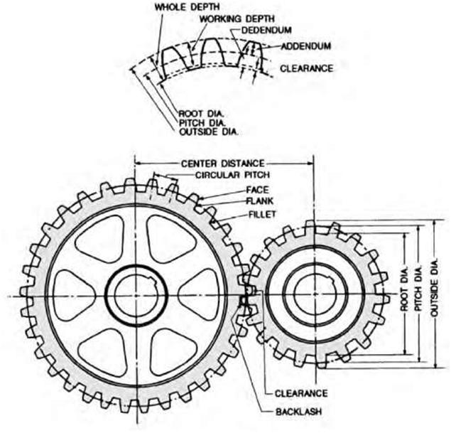
| Root The root is the surface of the thread corresponding to the minor diameter of an external thread and the major diameter of an internal thread. It represents the bottom or inner surface joining the sides of two adjacent threads. Depth The depth is the distance from the root of a thread to the crest, measured perpendicularly to the axis. Pitch The pitch is the distance from any point on the screw thread to a corresponding point on the next thread measured parallel to the axis. For example, nuts and bolts need to have the same pitch and diameter if they are to be used together. Lead The lead is the distance a screw thread advances in one complete turn, measured parallel to the axis. On a single-thread screw the lead is equal to the pitch; on a double-thread screw the lead is twice the pitch; on a triple-thread screw the lead is three times the pitch. Gears Gears are enhanced assembly relationships and work by determining a relationship (or ratio) between adjacent parts, such as gears and pulleys. Gears efficiently solve motion between related components without the need to define physical contact relationships. They can be used to describe rotary to rotary (gears), rotary to linear (rack and pinion), or linear to linear (telescopic or hydraulic cylinder) relationships. When gears are drawn on machine drawings, the drafter usually draws only enough gear teeth to identify the necessary dimensions. Figure 7.21 illustrates important gear nomenclature. The terms in the figure are explained in the following list: Pitch Diameter Pitch diameter (PD) is the diameter of the pitch circle (or line), which equals the number of teeth on the gear divided by the diametral pitch. It represents the diameter of a thread at an imaginary point where the width of the groove and the width of the thread are equal (i.e., the simple effective diameter of screw thread). It is approximately halfway between the major and minor diameters. This is the critical dimension of threading, as it determines the fit of the thread (not used for metric threads). Diametral Pitch Diametral pitch (DP) is the ratio of the number of teeth on a gear to the number of inches of pitch diameter or the number of teeth to each inch of pitch diameter (i.e,. the number of teeth on the gear divided by the pitch diameter). Diametral pitch is usually referred to as simply pitch. Number of Teeth The number of teeth (N) is the diametral pitch multiplied by the diameter of the pitch circle (DP x PD). |
|||
| Understanding Industrial Blueprints | 189 | ||
| Addendum Circle The addendum circle (A) is the circle over the tops of the teeth. Outside Diameter The outside diameter (OD) is the diameter of the addendum circle. Circular Pitch The circular pitch (CP) is the length of the arc of the pitch circle between the centers or corresponding points of adjacent teeth. Addendum The addendum (A) is the height of the tooth above the pitch circle or the radial distance between the pitch circle and the top of the tooth. Dedendum The dedendum (D) is the depth or that portion of a gear tooth from the pitch circle to the root circle of gear or the length of the portion of the tooth from the pitch circle to the base of the tooth. Chordal Pitch The chordal pitch is the distance from center to center of teeth measured along a straight line or chord of the pitch circle. Root Diameter The root diameter (RD) is the diameter of the circle at the root of the teeth. Clearance The clearance is the distance between the bottom of a tooth and the top of a mating tooth or the distance by which one object clears another or the clear space between them. Whole Depth The whole depth (WD) is the distance from the top of the tooth to the bottom, including the clearance. Face The face is the working surface of the tooth over the pitch line. Thickness The thickness is the width of the tooth, taken as a chord of the pitch circle. |
|||
| 190 | Chapter 7 | ||
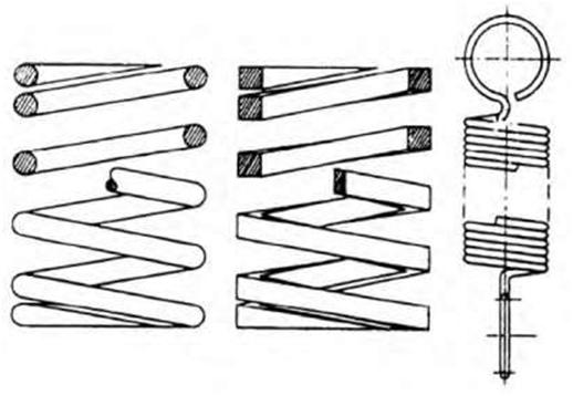
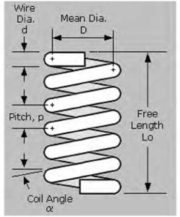
| Pitch Circle The pitch circle is the circle with the pitch diameter, the line (circle) of contact between two meshing gears. Working Depth The working depth is the greatest depth to which a tooth of one gear extends into the tooth space of another gear. Rack A rack may be compared to a spur gear that has been straightened out. The linear pitch of the rack teeth must equal the circular pitch of the mating gear. Helical Springs The helical spring, in which wire is wrapped in a coil that resembles a screw thread, is probably the most commonly used mechanical spring. There are three classifications of helical springs: compression, extension, and torsion. Drawings seldom show a true presentation of the helical shape; instead, they usually show springs with straight lines. Figure 7.22A shows several methods of spring representation including both helical and straight-line drawings. Figure 7.22B shows the use of typical helical spring nomenclature. A spring can be designed to carry, pull, or push loads. Twisted helical (torsion) springs are used in engine starters and hinges. Helical tension and compression springs have numerous uses, notably automobile suspension systems, gun-recoil mechanisms, and closing. In manufacturing coiled helical springs, the spring wire is wrapped around a mandrel that serves as a support; when seamless tubing is being extruded, a long mandrel forms the internal diameter. Helical springs, often called spiral springs, are probably the most common type of spring. They may be used in compression, extension, tension, or torsion. A spring used in compression tends to shorten in action, while a tension spring lengthens in action. Torsion springs, which transmit a twist instead of a direct pull, operate by a coiling or an uncoiling action. In addition to straight helical springs, cone, double-cone, keg, and volute springs are classified as helical. These types of springs are usually used in compression. 7.5 RECOMMENDED PRACTICE |
|||
| With industrial drawings and blueprint reading, as with other types of graphical representation, it is always advisable to follow the best industry practices current at the time: 1. Draw one part to one sheet of paper. If this is not practical, apply enough spacing between parts and draw all parts using the same scale. Otherwise, the scale should be clearly noted under each part’s drawing. Standard parts such as bolts, nuts, pins, and bearings do not require detail drawings. 2. Always use decimals. 3. Lettering should be all in capitals. 4. Select a front view that best describes the part. |
|||
| Understanding Industrial Blueprints | 191 | ||
 |
|||
| Figure 7.21 Gear nomenclature used in machine blueprints. | |||
| 5. Omit hidden lines unless absolutely necessary to describe the shape of the object. 6. Consider data and dimensioning schemes based on feature relationships. 7. Place dimensions between views where possible. 8. Where possible, minimize mathematical equations. 9. Do not dimension hidden lines. 10. Check that the product is designed for manufacturability and that an inspection process is in place to check dimension accuracy. |
|||
| 192 | Chapter 7 | ||
 |
|||
| Figure 7.22A Common types of helical springs. | |||
 |
|||
| Figure 7.22B | Typical helical spring nomenclature. | ||
| Understanding Industrial Blueprints 193 11. Avoid duplicating dimensions; use reference dimensions if necessary to duplicate. 12. Dimension lines should not cross other dimension lines. 13. Dimension lines should not cross extension lines. 14. No dimensions should appear on the body of a part. Offset 0.38 inch from the object outline. 15. Place all dimensions for the same feature in one view if possible. 16. Extension lines can cross extension lines. 17. Use center marks in view(s) only where a feature is dimensioned. 18. Use centerlines and center marks in views only if a feature is being dimensioned or referenced; otherwise omit. 19. When multiples of the same feature exist in a view, dimension only one of the features and label as “NumberX DIM,” meaning that the feature exists in that view a certain number of times. For example, “4X .250” implies that in the view, there are four like dimensions for the dimensioned feature. 20. Minimize the use of centerlines between holes; they add little value and clutter the object being drawn. |
||
| 7.6 STANDARDS The main international standards organizations for geometrical dimensioning and tolerancing are: ASME ANSI ISO For blueprint production, whether the print is drawn by a human hand or by computer-aided drawing (CAD) equipment, the American industry has adopted a new standard, ANSI Y14.5M. It standardizes the production of prints from the simplest on-site handmade job to single or multiple-run items produced in a machine shop with computer-aided manufacturing (CAM) software. There exist standards and practices for creating technical drawings of mechanical parts and assemblies. The governing agency mainly responsible for setting the standards in the United States is ASME. There are a number of documents that cover various aspects of mechanical drawings,including: ASME Y14.100 -2004 Engineering Drawing Practices ASME Y14.4M -1989 Pictorial Drawing ASME Y14.3M -Multi- and Sectional View Drawings ASME Y14.1-1995 Decimal Inch Drawing Sheet Size and Format ASME Y14.5M-1994 Geometric Dimensioning and Tolerancing ASME Y14.13M-1981 Mechanical Spring Representation It is important that these standards are implemented and followed by the drafter to ensure that the drawings are correctly interpreted by others. |
||

good job with info. Had a person use the term { Industrial } blue prints. I thought I was thinking the right thoughts. Thanks … I was on same page . I have always thought it as Manufacturing blue prints… Ansi Y14… and so on… Thanks again for good info. Ed.