

| 9.1 OVERVIEW | |||
|
A schedule as applied to construction working drawings is an organized method of presenting general notes or lists of materials, building components (doors, windows, etc.), equipment, and so forth in a drawing in tabulated form. The main purpose of incorporating schedules into a set of construction documents is to provide clarity, location, sizing, materials, and information on the designation of doors, windows, roof finishes, equipment, plumbing, and electrical fixtures. Properly done, schedules help keep drawings from becoming cluttered with too much printed information or notes and have proven to be great time-saving devices for the person preparing the drawing as well as the architect, engineer, contractor, and workers on the site. This chapter is intended to assist the reader in interpreting tabulated information on blueprint drawings. It should be understood that schedules and specifications give specific details about actual items, while drawings generally show the size and location of the item. Schedules are generally organized in a drawing set such that they are near the discipline to which they are related. There are several different approaches to setting up a schedule; it may include all or some of the following information about the product: Vendor’s name Product name Model number Size Quantity Rough opening size Material Color Many different items or features may be described in schedules: some examples are, doors, windows, lintels, columns, beams, electrical equipment or fixtures, plumbing and mechanical equipment, room finish information, and appliances. These schedules are essentially tables (i.e., a box of columns |
|||
| Copyright © 2009 by The McGraw-Hill Companies, Inc. Click here for terms of use. | 219 | ||
| 220 | Chapter 9 | |||||||||||||||||||||||||||||||||||||||||||||||||||||||||||||||||||||||||||||||||||||||||||||||||||||||||||||||||||||||||
|
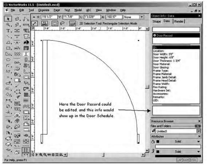
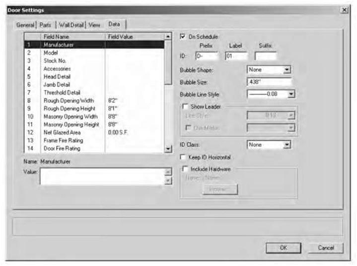
and rows) that list information about specific items. Schedules allow you to quickly refer to a specific item. On large commercial projects schedules may require several sheets. The exact method of representation depends upon individual company standards. While schedules are usually presented in tabulated form, they are often accompanied by pictorial schedules for additional clarity. This feature is discussed below. There are many software systems today that allow you to make schedules easily and quickly. For example, in Architectural Desktop schedules are constructed of tabulated data that are extracted from the individual objects in your drawings. To simplify matters, Autodesk has built into ADT2 a good number of schedules that can be used as is or as a basis for customizing. VectorWorks Architect is another excellent program for generating door and window schedules. Figure 9.1 illustrates some of the procedures used to generate door and window schedules using VectorWorks CAD software. |
||||||||||||||||||||||||||||||||||||||||||||||||||||||||||||||||||||||||||||||||||||||||||||||||||||||||||||||||||||||||||
|
||||||||||||||||||||||||||||||||||||||||||||||||||||||||||||||||||||||||||||||||||||||||||||||||||||||||||||||||||||||||||
| Figure 9.1A An example of a door schedule generated using VectorWorks CAD software (source: VectorWiki). | ||||||||||||||||||||||||||||||||||||||||||||||||||||||||||||||||||||||||||||||||||||||||||||||||||||||||||||||||||||||||||
| Understanding Schedules | 221 | ||
 |
|||
| Figure 9.1B An example of a door schedule generated using VectorWorks CAD software (source: VectorWiki). | |||
| 9.2 DOOR AND WINDOW SCHEDULES | |||
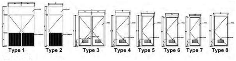
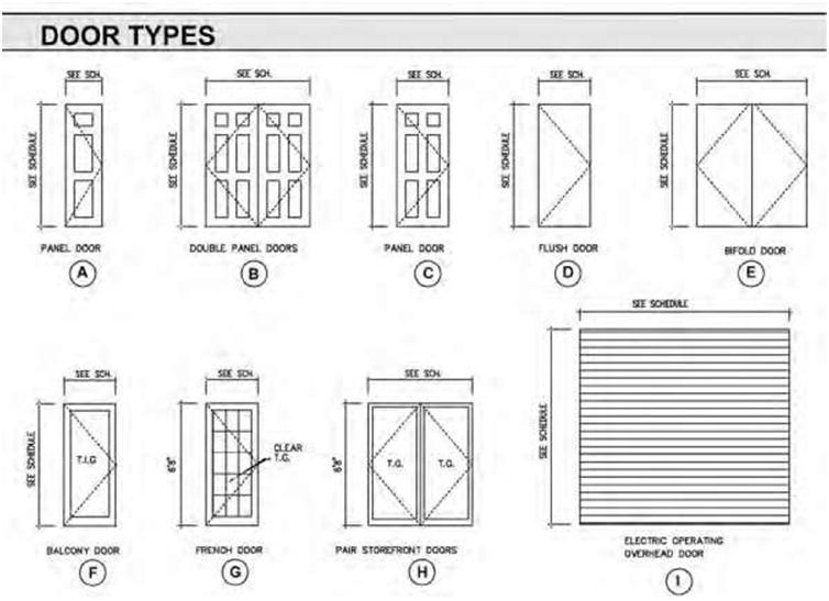
| Door Schedules Door schedules typically indicate the model or mark, quantity, size, thickness, type, material, function, frame material, fire rating, and remarks. Examples of typical door schedules are shown in Figures 9.2A, B, and C. Sometimes tabulated door and window schedules are accompanied by graphic schedules— in pictorial form with elevations of the door or window types—to facilitate identification (Figures 9.3A and B). Door schedules may include information regarding glazing and louvers if appropriate. Commercial |
|||
| 222 | Chapter 9 | ||
 |
|||
| Figure 9.1C An example of a door schedule generated using VectorWorks CAD software (source: VectorWiki). | |||
|
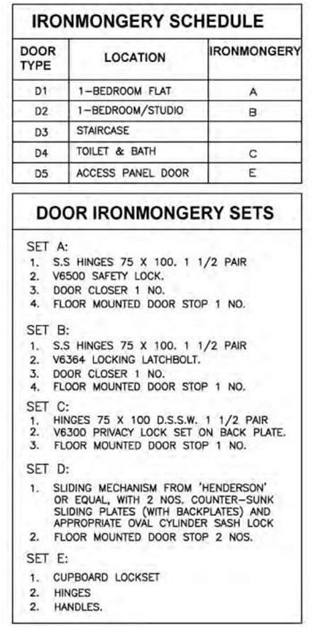
door schedules may also include hardware and door frame data and key codes. In some cases the designer may decide to show the ironmongery in a separate schedule (Figure 9.4). Door schedules are generally longer and more detailed than window schedules. Doors and door function are usually critical to the success of the building. Doors are in constant use and serve many different functions, including passage, privacy, and security. Doors may be identified as to size, type, and style, with code numbers placed next to each symbol in a plan view. This code number or mark is then entered on a line in a door schedule, and the principal characteristics of the door are entered in successive columns along the line. The “quantity” column allows a quantity check on doors of the same design as well as the total number of doors required. By using a number with a letter, you will find that the mark serves a double purpose: The number identifies the floor on which the door is located, and the letter identifies the door design. The “remarks or comments” column allows identification by type (panel or flush), style, and material. The schedule is a convenient way of presenting pertinent data without having to refer to the specification. |
|||
| Understanding Schedules | 223 | ||||||||||||||||||||||||||||||||||||||||||||||||||||||||||||||||||||||||||||||||||||||||||||||||||||||||||||||||||||||||||||||||||||||||||||||||||||||||||||||||||||||||||||||||||||||||||||||||||||||||||||||||||||||||||||||||||||||||||||||||||||||||||||||||||||||||||||||||||||||||||||||||||||||||||||||||||
|
|||||||||||||||||||||||||||||||||||||||||||||||||||||||||||||||||||||||||||||||||||||||||||||||||||||||||||||||||||||||||||||||||||||||||||||||||||||||||||||||||||||||||||||||||||||||||||||||||||||||||||||||||||||||||||||||||||||||||||||||||||||||||||||||||||||||||||||||||||||||||||||||||||||||||||||||||||
| Figure 9.2A Examples of various door-schedule formats. The information on a door schedule is dictated by the complexity and size of the project. | |||||||||||||||||||||||||||||||||||||||||||||||||||||||||||||||||||||||||||||||||||||||||||||||||||||||||||||||||||||||||||||||||||||||||||||||||||||||||||||||||||||||||||||||||||||||||||||||||||||||||||||||||||||||||||||||||||||||||||||||||||||||||||||||||||||||||||||||||||||||||||||||||||||||||||||||||||
|
|||||||||||||||||||||||||||||||||||||||||||||||||||||||||||||||||||||||||||||||||||||||||||||||||||||||||||||||||||||||||||||||||||||||||||||||||||||||||||||||||||||||||||||||||||||||||||||||||||||||||||||||||||||||||||||||||||||||||||||||||||||||||||||||||||||||||||||||||||||||||||||||||||||||||||||||||||
| Figure 9.2B Examples of various door-schedule formats. The information on a door schedule is dictated by the complexity and size of the project. | |||||||||||||||||||||||||||||||||||||||||||||||||||||||||||||||||||||||||||||||||||||||||||||||||||||||||||||||||||||||||||||||||||||||||||||||||||||||||||||||||||||||||||||||||||||||||||||||||||||||||||||||||||||||||||||||||||||||||||||||||||||||||||||||||||||||||||||||||||||||||||||||||||||||||||||||||||
| 224 | Chapter 9 | |||||||||||||||||||||||||||||||||||||||||||||||||||||||||||||||||||||||||||||||||||||||||||||||||||||||||||||||||||||||||||||||||||||||||||||||||||||||||||||||||||||
| DOOR SCHEDULE | ||||||||||||||||||||||||||||||||||||||||||||||||||||||||||||||||||||||||||||||||||||||||||||||||||||||||||||||||||||||||||||||||||||||||||||||||||||||||||||||||||||||
| MARK | SIZE | LATCH TYPE MAT L FINISH DEVICE | FRAME THOLD CLOSER REMARKS | |||||||||||||||||||||||||||||||||||||||||||||||||||||||||||||||||||||||||||||||||||||||||||||||||||||||||||||||||||||||||||||||||||||||||||||||||||||||||||||||||||
| 101 PR-3-0 X 6-8 X 1 3/4 A WD/GL PTD KEY LOCK WD ALUM 102 PR-3-0 X 6-8 X 1 3/4 A WD/GL PTD KEY LOCK WD ALUM |
CLOSER CLOSER CLOSER CLOSER CLOSER |
TRANSOM, SCREEN DOORS TRANSOM, SCREEN DOORS 60 MIN FIRE RATING CHAIN STOP SCREEN DOOR |
||||||||||||||||||||||||||||||||||||||||||||||||||||||||||||||||||||||||||||||||||||||||||||||||||||||||||||||||||||||||||||||||||||||||||||||||||||||||||||||||||||
| 103 3-0 X 6-8 X 1 3/4 C WD/GL PTD PASSAGE RATED HM | ||||||||||||||||||||||||||||||||||||||||||||||||||||||||||||||||||||||||||||||||||||||||||||||||||||||||||||||||||||||||||||||||||||||||||||||||||||||||||||||||||||||
|
HM HM HM |
ALUM ALUM ALUM |
||||||||||||||||||||||||||||||||||||||||||||||||||||||||||||||||||||||||||||||||||||||||||||||||||||||||||||||||||||||||||||||||||||||||||||||||||||||||||||||||||||
| WD | CLOSER | SCREEN DOORS HOLDOPEN AT 180 DEG. HOLD OPEN AT 180 DEG. 60 MIN FIRE RATING SCREEN DOORS |
||||||||||||||||||||||||||||||||||||||||||||||||||||||||||||||||||||||||||||||||||||||||||||||||||||||||||||||||||||||||||||||||||||||||||||||||||||||||||||||||||||
| ALUM | ||||||||||||||||||||||||||||||||||||||||||||||||||||||||||||||||||||||||||||||||||||||||||||||||||||||||||||||||||||||||||||||||||||||||||||||||||||||||||||||||||||||
| WD | ALUM |
CLOSER CLOSER CLOSER CLOSER CLOSER CLOSER |
||||||||||||||||||||||||||||||||||||||||||||||||||||||||||||||||||||||||||||||||||||||||||||||||||||||||||||||||||||||||||||||||||||||||||||||||||||||||||||||||||||
| ALUM | ||||||||||||||||||||||||||||||||||||||||||||||||||||||||||||||||||||||||||||||||||||||||||||||||||||||||||||||||||||||||||||||||||||||||||||||||||||||||||||||||||||||
| ALUM | SCREEN DOORS | |||||||||||||||||||||||||||||||||||||||||||||||||||||||||||||||||||||||||||||||||||||||||||||||||||||||||||||||||||||||||||||||||||||||||||||||||||||||||||||||||||||
| Figure 9.2C Examples of various door-schedule formats. The information on a door schedule is dictated by the complexity and size of the project. | ||||||||||||||||||||||||||||||||||||||||||||||||||||||||||||||||||||||||||||||||||||||||||||||||||||||||||||||||||||||||||||||||||||||||||||||||||||||||||||||||||||||
|
The “mark” heading in door and window schedules usually refers to the window or door location on the blueprint. In other words, on the floor plan of each level of the house, windows and doors are drawn within the wall layout. The architect assigns a number to each window and door beginning with 1. |
||||||||||||||||||||||||||||||||||||||||||||||||||||||||||||||||||||||||||||||||||||||||||||||||||||||||||||||||||||||||||||||||||||||||||||||||||||||||||||||||||||||
| Understanding Schedules | 225 | ||
 |
|||
| DOORS Figure 9.3A An example of a pictorial schedule that often accompanies tabulated door schedules. |
|||
 |
|||
| Figure 9.3B An example of a pictorial schedule that often accompanies tabulated door schedules. | |||
| 226 | Chapter 9 | ||
 |
|||
| Figure 9.4 An example of a simple ironmongery schedule for a residence. | |||
| Understanding Schedules | 227 | ||||||||||||||||||||||||||||||||||||||||||||||||||||||||||||||||||||||||||||||||||||||||||||||||||||||||||||||||||||||||||||||||||||||||||||||||||||||||||||||
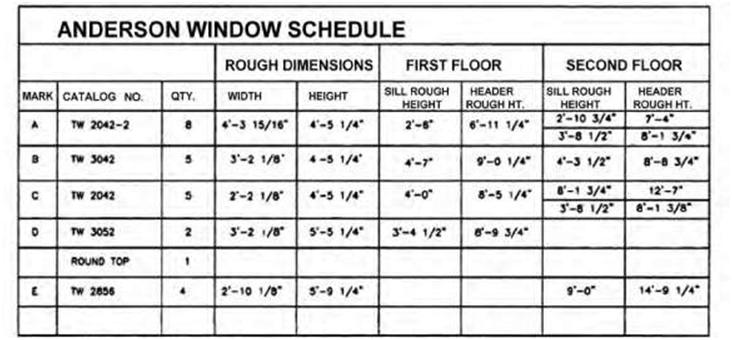
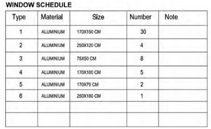
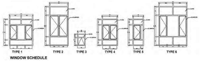
| Window Schedules A window schedule is similar to a door schedule in that it provides an organized presentation of the pertinent window characteristics. Window schedules include quantity, type, model, manufacturer, size, rough opening, materials, glazing, and finish. There is also usually a column for remarks/notes (Figure 9.5). Also, like door schedules, tabulated schedules cannot always clearly define a specific window. In this case you can add to a schedule a callout with a pictorial drawing of a window adjacent to the window schedule (Figure 9.6). |
|||||||||||||||||||||||||||||||||||||||||||||||||||||||||||||||||||||||||||||||||||||||||||||||||||||||||||||||||||||||||||||||||||||||||||||||||||||||||||||||
|
|||||||||||||||||||||||||||||||||||||||||||||||||||||||||||||||||||||||||||||||||||||||||||||||||||||||||||||||||||||||||||||||||||||||||||||||||||||||||||||||
| Figure 9.5A A type of window schedule. | |||||||||||||||||||||||||||||||||||||||||||||||||||||||||||||||||||||||||||||||||||||||||||||||||||||||||||||||||||||||||||||||||||||||||||||||||||||||||||||||
 |
|||||||||||||||||||||||||||||||||||||||||||||||||||||||||||||||||||||||||||||||||||||||||||||||||||||||||||||||||||||||||||||||||||||||||||||||||||||||||||||||
| Figure 9.5B A type of window schedule. | |||||||||||||||||||||||||||||||||||||||||||||||||||||||||||||||||||||||||||||||||||||||||||||||||||||||||||||||||||||||||||||||||||||||||||||||||||||||||||||||
| 228 | Chapter 9 | ||
 |
|||
| Figure 9.5C A type of window schedule. | |||
 |
|||
| Figure 9.6 A pictorial representation of a window schedule. | |||
| Understanding Schedules 229 9.3 FINISH SCHEDULE |
||
|
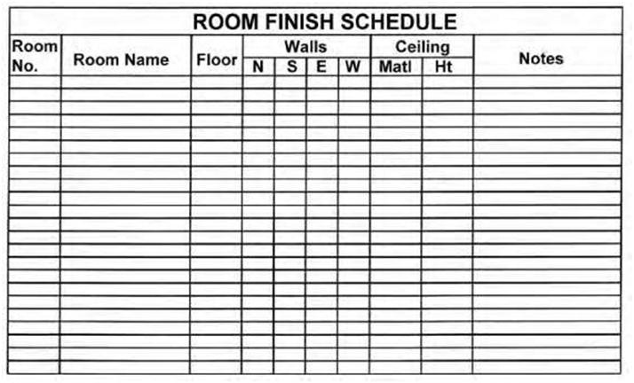
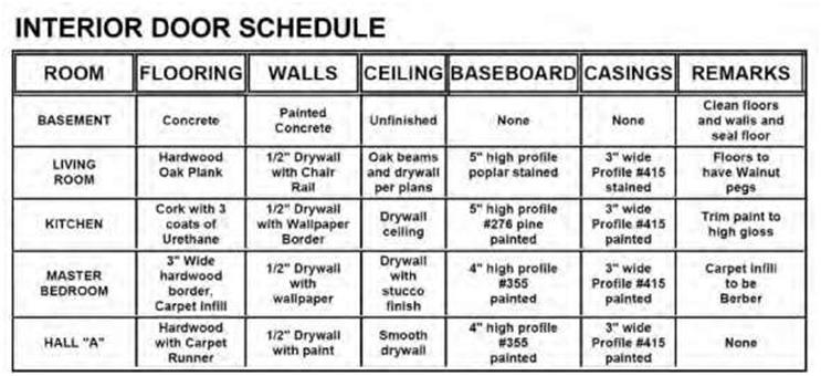
A finish schedule specifies the interior finish material for each room, space, and floor in the building. The finish schedule provides information for the walls, floors, ceilings, baseboards, doors, and window trim. Finish schedules can vary in both format and complexity. A single-family home will generally consist of a limited number of finishes. Commercial buildings, on the other hand, may consist of a larger number of wall and floor finishes. The larger finish schedules are normally in a matrix format and are typically divided into categories such as by space use or by floor. The Y axis lists the spaces, and the X axis is sectioned into floors, base, walls, and ceilings. The room finish schedule should have an entry for every room and hallway in the house or room addition. Finish schedules will also list ceiling heights and marks for each space. The marks can constitute room numbers. Typical examples of finish schedules are shown in Figure 9.7. |
||
 |
||
| Figure 9.7A An example of one type of interior-finish schedule. | ||
| 230 | Chapter 9 | ||||||||||||||||||||||||||||||||||||||||||||||||||||||||||||||||||||||||||||||||||||||||||||||||||||||||||||||||||||||||||||||||||||||||||||||||||||||||||||||||||||||||||||||||||||||||||||||||||||||||||||||||||||||||||||||||||||||||||||||||||||||||||||||||||
|
|||||||||||||||||||||||||||||||||||||||||||||||||||||||||||||||||||||||||||||||||||||||||||||||||||||||||||||||||||||||||||||||||||||||||||||||||||||||||||||||||||||||||||||||||||||||||||||||||||||||||||||||||||||||||||||||||||||||||||||||||||||||||||||||||||
| Figure 9.7B An example of one type of interior-finish schedule. | |||||||||||||||||||||||||||||||||||||||||||||||||||||||||||||||||||||||||||||||||||||||||||||||||||||||||||||||||||||||||||||||||||||||||||||||||||||||||||||||||||||||||||||||||||||||||||||||||||||||||||||||||||||||||||||||||||||||||||||||||||||||||||||||||||
 |
|||||||||||||||||||||||||||||||||||||||||||||||||||||||||||||||||||||||||||||||||||||||||||||||||||||||||||||||||||||||||||||||||||||||||||||||||||||||||||||||||||||||||||||||||||||||||||||||||||||||||||||||||||||||||||||||||||||||||||||||||||||||||||||||||||
| Figure 9.7C An example of one type of interior-finish schedule. | |||||||||||||||||||||||||||||||||||||||||||||||||||||||||||||||||||||||||||||||||||||||||||||||||||||||||||||||||||||||||||||||||||||||||||||||||||||||||||||||||||||||||||||||||||||||||||||||||||||||||||||||||||||||||||||||||||||||||||||||||||||||||||||||||||
| Understanding Schedules | 231 | ||
| 9.4 HVAC SCHEDULES | |||
|
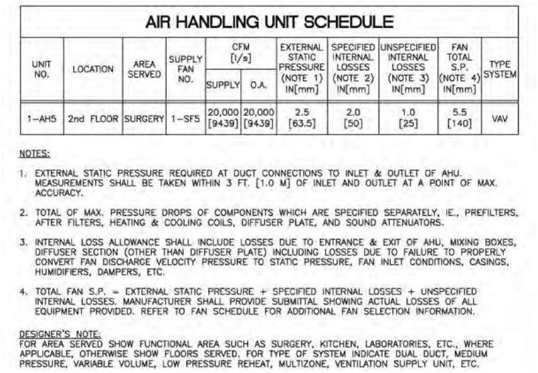
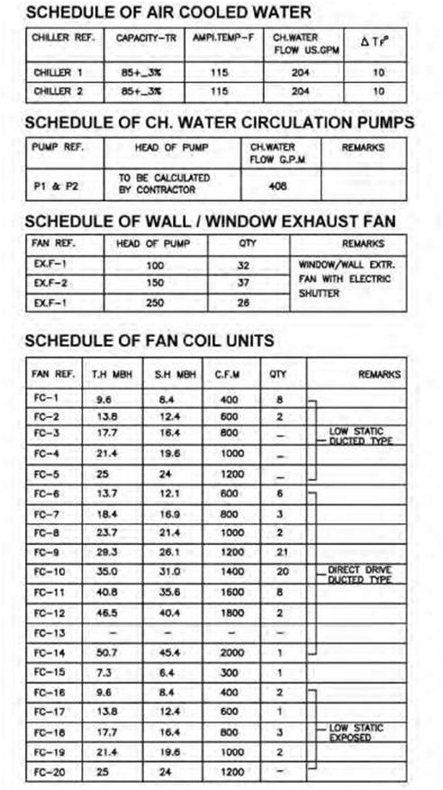
There are many different types of HVAC schedules, which may include air-handling units, fan-coil units, chiller schedules, etc. These are prepared by the mechanical consultant. HVAC systems are typically either self-contained package units or central systems. Package units include roof top systems, air-to-air heat pumps, and air-conditioning units for rooms. Central systems usually consist of a combination of central-supply subsystem and multiple end-use zone systems (fan systems or terminal units). Figures 9.8A and B show examples of different types of HVAC schedules. |
|||
 |
|||
| Figure 9.8A A simple example of an air-handling-unit schedule. Notice the significant number of notes that accompany the schedule. These are critical to a proper understanding of the requirements. | |||
| 232 | Chapter 9 | ||
 |
|||
| Figure 9.8B Examples of various types of schedules relating to HVAC drawings. | |||
| Understanding Schedules | 233 | ||
| 9.5 GRILLE/DIFFUSER SCHEDULES | |||
|
Grille and diffuser schedules generally show the manufacturer and catalog/model number of each grille and diffuser. They also show the dimensions of each as well as the volume of air in cubic feet per minute (CFM) that each will handle, the quantity required, and the location for installation. A column for notes/remarks is typically included to facilitate the installation of the item. 9.6 LIGHTING-FIXTURE AND ELECTRICAL SCHEDULES |
|||
|
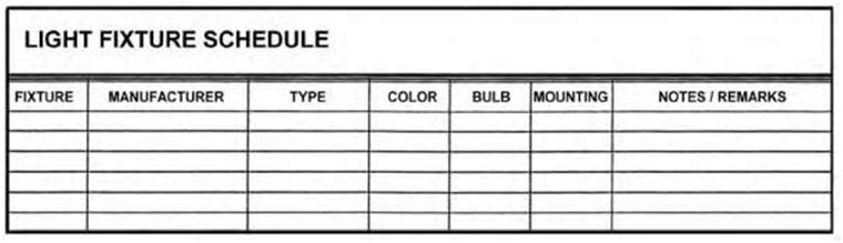
Lighting-fixture schedules are generally used to list the fixture types and identify each fixture type on the drawing of a given project by number. The manufacturer and identification number of each type are given along with the number, size, and type of the lamps for each. One can include a “mounting” column to indicate whether the fixture is wall-mounted, surfaced-mounted on the ceiling, or recessed. Alternatively, this information can be included in the “remarks” column. Also included in this column is information relating to the mounting height above the finished floor, in the case of a wall-mounted lighting fixture, or any other pertinent data for the proper installation of the fixtures (Figure 9.9). Electrical general notes are placed on the first and subsequent sheets of the electrical drawings. They contain items that are common to all electrical items and may also include information regarding coordination of other trades with the electrical trades Electrical notes are normally contained on each sheet as required and are relevant to that particular sheet only. They are also used to give specific location and direction regarding electrical issues. 9.7 PANEL-BOARD SCHEDULES |
|||
|
Panel-board schedules are generally found on electrical drawings and are used mainly to indicate relevant information on the service-panel boards within the building. A panel-board schedule should provide sufficient data to identify the panel number (as indicated on the drawings) and the type of cabinet (whether surface-mounted or flush). It should also provide relevant data regarding the panel main bus bars and/or circuitbreakers as well as the number and type of circuitbreakers contained in the panel board and the components fed by each. This type of schedule, however, does not furnish detailed information for the individual circuits (e.g., wire sizes or number of outlets on the circuit); this information needs to be shown elsewhere on the drawing, such as in the plan view or power-riser diagrams. 9.8 MISCELLANEOUS SCHEDULES AND NOTES |
|||
|
Other types of schedules used depend on office procedure and the type of project in hand. Material schedules are used usually to list the approximate quantities of materials needed to complete a project. These schedules are often used for estimating small construction projects such as residential buildings and should not be taken to reflect the exact amount of materials needed. Material schedules are mainly used for guidance. |
|||
| 234 Chapter 9 | ||
 |
||
| Figure 9.9 An example of a a typical lighting-fixture schedule. | ||
|
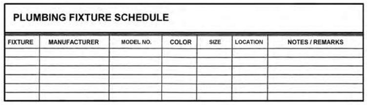
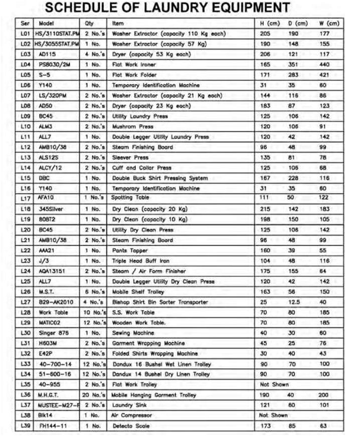
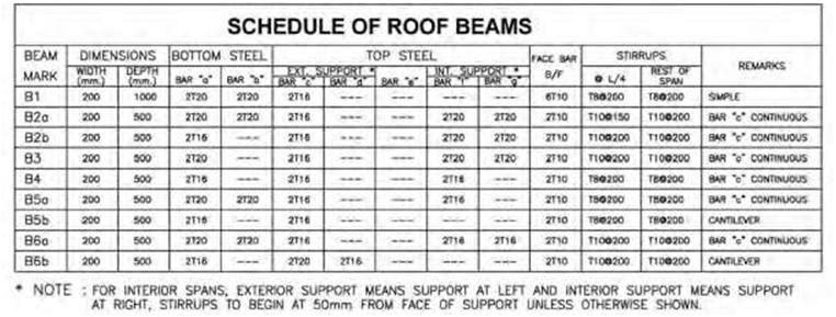
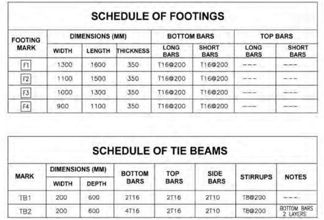
Appliance and plumbing-fixture schedules are similar to other types of schedules. For example, the appliance schedule would list each appliance from top to bottom in the first column. Other columns would list manufacturer and model number, color, special features, options, etc. The plumbing-fixture schedule would list the room, fixtures for that room, manufacturer and model number, color, finish, handle options, etc (Figure 9.10). If plumbing-fixture schedules or appliance schedules are not used in a project, the fixture types, manufacturers, catalog numbers, and other information needed must be included in the project specifications. Figure 9.11 is an example of an equipment schedule for a commercial laundry, and Figures 9.12 shows examples of structural/civil-engineering schedules for roof beams, footings, and tie beams. Usually the specifications will augment information found in the schedules. Examples of information usually found in the specifications include the window manufacturer, the type and manufacturer of the door hardware, and the type and manufacturer of paint for the trim. 9.9 NOTES |
||
| Notes are a pivotal aspect of construction drawings, as they often contain critical information regarding the project. Notes should be clear, concise, and easily understood. They do not typically contain technical information but rather clarify and explain conditions or requirements of the project. There are two basic types of notes: 1. General notes are usually placed at the beginning of the drawings relating to a specific trade or discipline. They include all notes on the drawing not accompanied by a leader and an arrowhead. They are used essentially to explain and specify certain conditions relative to that discipline or the project as a whole. 2. Key notes are contained on a particular page or sheet as needed and relate only to that sheet. |
||
| Understanding Schedules 235 | ||
 |
||
| Figure 9.10 An example of a plumbing-fixture schedule. | ||
|
Project general notes are typically placed near the beginning of the drawing set, usually at least 3 inches below the “revision” block in the right-hand side of the first sheet. The purpose of these notes is to give additional information that clarifies a detail or explains how a certain phase of construction is to be performed. They usually include site issues such as occupancy, security, parking, access, and other general site-related issues ( including permits and posting). Architectural general notes are typically placed on the first and subsequent sheets of the architectural drawings. They contain items that are common to all architectural elements. They may also contain information regarding coordination with other trades. Architectural key notes are contained on each sheet as required and are relevant to that particular sheet only. They provide additional description of architectural details and are typically used with leader lines to show exact detail locations. All notes, along with the specifications, should be carefully read during the planning of the project. |
||
| 236 | Chapter 9 | ||
 |
|||
| Figure 9.11 A laundry-equipment schedule for a small commercial laundry. | |||
| Understanding Schedules | 237 | ||
 |
|||
| Figure 9.12A An example of a schedule used in civil- and structural-engineering drawings. | |||
 |
|||
| Figure 9.12B An example of a schedule used in civil- and structural-engineering drawings. | |||