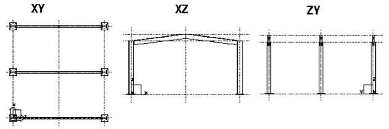
Introduction There are several ways to create views in Tekla Structures. For example, you can create views: • of the entire structure • of selected part(s) and component(s) • along the grid lines Each view has properties which define its appearance. You can change the appearance of a view after you create it so choose the creation method that suits you. This section describes the view-specific properties. You can open the view properties dialog box for each view, to view or modify the properties. |
|||||
T | Unnamed views disappear when you close them. | ||||
You can have up to nine views on the screen at the same time. If you try to open more than nine views, Tekla Structures displays a warning. If the view does not appear, check how many views you have open. To switch between views, press Ctrl+Tab. |
|||||
V | |||||
View plane | ||||
Basic view plane | Each view has a view plane on which the grids are visible and points are represented as yellow crosses. Basic views are those parallel to the global basic planes, i.e. xy, xz, and zy. In basic views two axes always define the view plane and they appear in the plane name. The third axis is perpendicular to the view plane. It does not appear in the plane name. In the basic plane view, the model is shown from the direction of that third axis. The view plane options for basic views are: |
|||
View plane coordinate Other views |
For basic views, you also define at which distance from the global origin the view plane is in direction of the third axis. The view plane coordinate equals this distance. For view types other than basic views, you define the view plane and coordinate by picking points, e.g. With three points, or they are defined automatically according to the chosen creation method/command, e.g. To work plane. You can change the view plane by moving it like any other object. Click anywhere on the plain background, right-click and select Move Special > Linear… from the pop-up menu. |
|||
Moving the view plane | ||||
■s | Moving a view plane may result in a situation such that view depth and work area do not intersect and thus nothing can be seen in the window. | |||
View properties | ||||
Naming views Tekla Structures numbers views in order of creation, so you do not have to give each view a specific name. You should give a view a unique name if you need to open it in later sessions. When you exit the model, Tekla Structures only saves named views. Tekla Structures does not save unnamed views when you close them. |
||||
In multi-user mode, it is very important to give views unique names. If several users have different views with the same name, the view settings of one user may randomly override the settings of another user. | ||||
• Rendered Part surfaces are displayed, i.e. parts are not transparent. |
|||||
• Rendered (Dark colors) Parts are not transparent. Part outlines are displayed with brighter color, and part surfaces with darker color than in the Rendered option. |
|||||
• | In rendered views, use the shortcuts Ctrl+1…5 and Shift+1…5 to set the desired representation for parts in the model and components. | ||||
View angle | Projection If you choose the rendered view type, the projection can be: • Orthogonal All objects are of equal size (no perspective). When you zoom, text and point size remains the same. In addition, the zoom remains on part surfaces. • Perspective Distant objects appear smaller than close ones, as do text and points. You can zoom, rotate the model, or fly through it. Views can be: • Plane • 3d |
||||
Use the shortcut Ctrl+P or click View > Switch to 3D / Plane to switch between 3D and plane view. | |||||
Rotation | Rotation is view-specific. You can rotate the model in 3D views using the mouse and keyboard or by defining the rotation angle in the View properties dialog box. You can specify rotation angles around the z axis and around the x axis. | ||||
View depth | Every view has depth, which is the thickness of the displayed slice of model. You can define the depth separately upwards and downwards from the view plane. The objects within the displayed depth and the work area are visible in the model. However, objects created after the view are visible also outside the view depth. | ||||
Defining grid view properties | |||||
Number of views |
Grid views are views along the grid lines. Before creating grid views, you can define how many views Tekla Structures will create, how it will name the views, and which view properties it will use. There are four options for the number of views: • None Tekla Structures does not create any views. • One (First) Tekla Structures only creates the view closest to the grid origin. • One (Last) Tekla Structures only creates the view furthest from the grid origin. • All Tekla Structures creates all views in grid planes in the relevant direction. View names consist of a prefix and a grid label, e.g. plan +3000. If the View name prefix field is left empty, no prefix is used. Tekla Structures adds a dash and a running number to the view name if view names are otherwise identical. Each view plane has its own view properties. You can load the properties from the current view properties with the option or from saved view properties. The Show… button displays the view properties. |
||||
View name prefix | |||||
View properties | |||||
Creating and modifying views | |||||
Creating |
When you create a new model, you can select the Create default view and grid checkbox to have Tekla Structures automatically create a grid and a view according to the saved standard properties. To create views, use the commands on the View menu. The following table lists the commands for creating views and gives a short description of each one: |
||||
Command | Icon Description | ||||
Create View of Model > 3D View… | Displays the Create 3D View dialog box and creates a 3D view. | ||||
Create View of Model > Using Two Points Create View of Model > Using Three Points |
Creates a view using two picked points. Creates a view using three picked points. |
||||
Create View of Model > On Work Plane | Creates a view of the current work plane. | ||||