
 |
|||||||||||||||||||||||||||||||||||
| Tekla Structures includes the following surface treatment tools in Detailing > Create Surface Treatment: | |||||||||||||||||||||||||||||||||||
|
|||||||||||||||||||||||||||||||||||
| Overlapping surface treatments |
When you create overlapping surface treatments, the smaller surface treatment overrides the larger one. The overlapping area is recognized in reports: only the topmost (visible) surface treatment is calculated. |
||||||||||||||||||||||||||||||||||
 |
|||||||||||||||||||||||||||||||||||
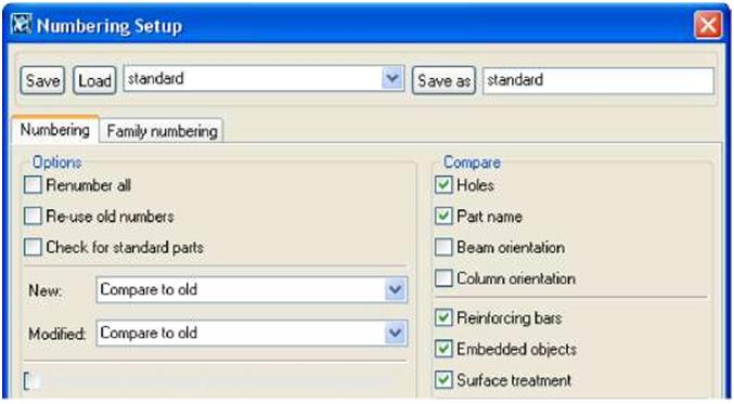
| Numbering | To have Tekla Structures include surface treatment in numbering, click Drawings & Reports > Numbering > Numbering Settings…, and select the Surface treatment checkbox on the Numbering tab. | ||||||||||||||||||||||||||||||||||
 |
|||||
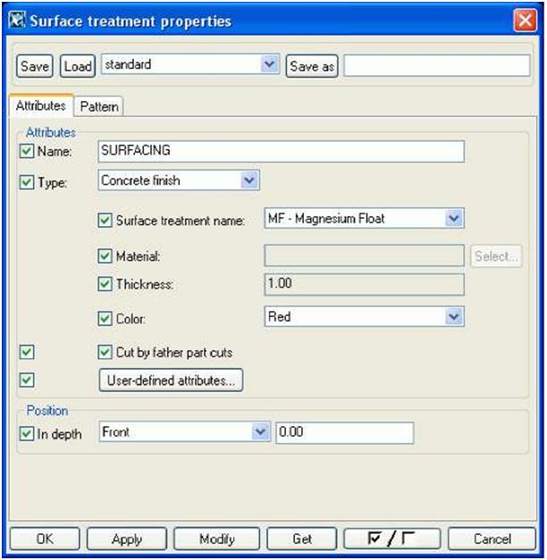
| 2. In the Type list box, select the type of surface treatment to use. 3. In the Surface treatment name list box, select the specific surface treatment. 4. Click the Select… button against Material to select a material from the catalog. 5. Enter the Thickness of the surface treatment. 6. Set the Color to use to display the surface treatment in rendered views. 7. In the At depth list box, select the location of the surface treatment. The options are Middle, Front, and Behind. 8. Click Apply or OK to save the surface treatment properties. To define the properties of a tiled surface treatment, continue as follows: 1. On the Attributes tab, select Tile surface from the Type list box. 2. On the Pattern tab, select the pattern from the Pattern type list box. 3. The Definition table lists the properties of the pattern type. |
|||||


|
||||||||||||||||||||||
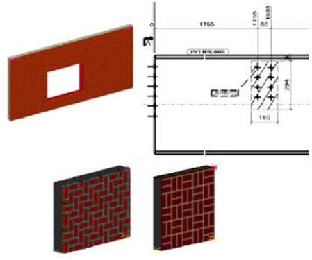
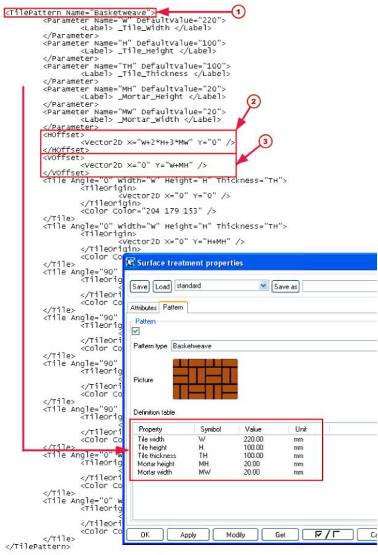
| Example pattern This example explains how the Basketweave tile pattern is defined in the definition TilePatternCatalog.xml file and shows how the pattern options appear on the Pattern tab of the Surface treatment properties dialog box: |
||||||||||||||||||||||
| 94 TEKLA STRUCTURES 14.0 Parts |
||||||||||||||||||||||
| TEKLA STRUCTURES 14.0 95 Parts |
||
 |
|||
| 96 | TEKLA STRUCTURES 14.0 Parts | ||
| PO The name of the pattern /T\ The size of the pattern block in the x direction, after which the pattern |
||
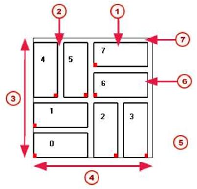
| repeats © The size of the pattern block in the y direction, after which the pattern repeats The Basketweave pattern block is made up of eight tiles: |
||
 |
||
| MJ Tile width f2J Mortar width f3J VOffset (4) HOffset Red marks indicate TileOrigin |
||
| ^^ Angle value for vertical tiles is 90 | ||
| f6J Tile height MM Mortar height | ||
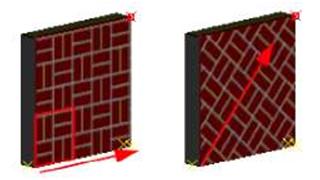
| The pattern is repeated in the x and y direction of the surface treatment, starting from the origin of the surface treatment. You can run the pattern in different x directions: | ||
| TEKLA STRUCTURES 14.0 97 Parts |
||
 |
||||||||||||||||||||||||||||||||||||||||||||||||||
| Defining your own tile patterns XML file To define your own tile patterns: 1. Open the TilePatternCatalog.xml file using any text editor. The file is located in the ..TeklaStructures\*version*\environments\*your_environment*\s ystem folder. 2. Add a new <TilePattern> element to the file. A <TilePattern> element must have <HOffset> and <VOffset> elements and at least one <Tile> element. Other elements are optional. You may find it easier to copy one of the existing elements, then change it suit your needs. The TilePatternCatalog.xml file can contain the following elements: |
||||||||||||||||||||||||||||||||||||||||||||||||||
|
||||||||||||||||||||||||||||||||||||||||||||||||||
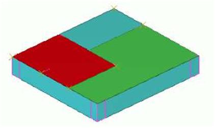
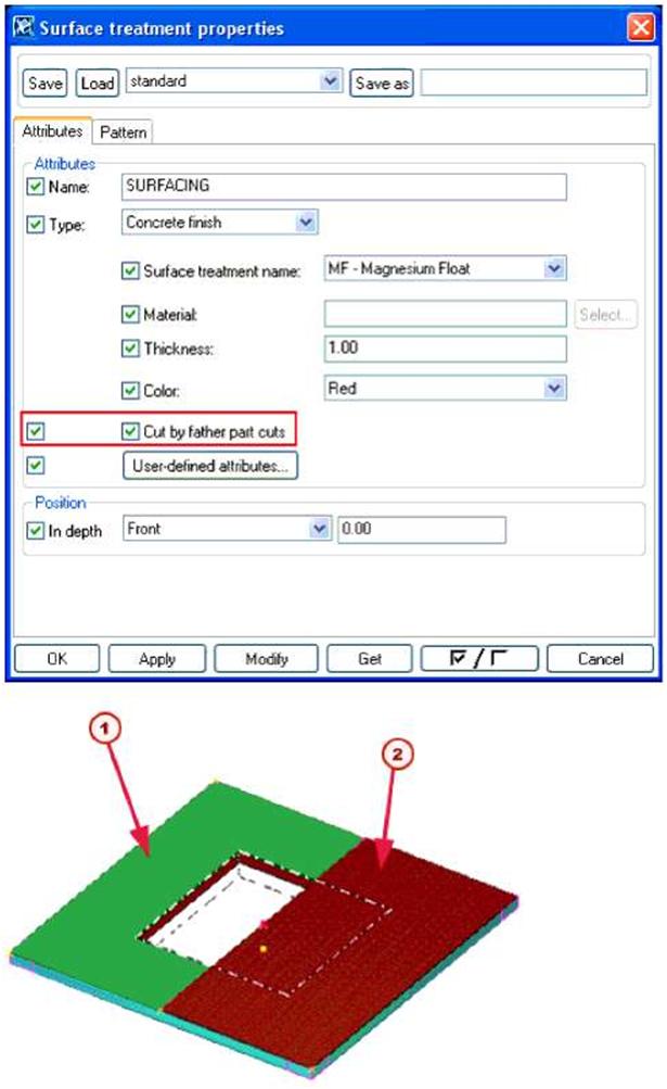
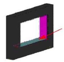
| 3. Repeat adding <TilePattern> elements for all the patterns you want to define. 4. Save the TilePatternCatalog.xml file. Adding surface treatment to parts with cuts and recesses To force Tekla Structures to consider openings and recesses in parts when adding surface treatment, select the Cut by father part cuts checkbox in the Surface Treatment Properties dialog box: |
||||||||||||||||||||||||||||||||||||||||||||||||||
 |
|||||
| /T\ The green surface treatment has the Cut by father part cuts checkbox | |||||
| selected | |||||
| /T\ The tiled surface treatment is not cut by the cut in the part: Cut by father | |||||
| part cuts is not selected. | |||||
| Surface treatment To to cut faces 1. 2. 3. 4. |
add surface treatment to cut faces: Click Detailing > Create Surface Treatment, and then click either To Part Face or To Selected Area on Part Face. Pick the origin of the surface treatment. Pick the direction. Select the cut face on which to apply the surface treatment: |
||||
 |
|||||
| 5. For the To Selected Area on Part Face option, pick the points to define the area of the surface treatment. | |||||
| rjl | If you use the To All Faces of Part command and select the Cut by father part cuts checkbox, Tekla Structures automatically adds surface treatment also to the cut faces. | ||||
| Cutting surface treatment | To define the cut depth of a polygon cut, for example, to cut thick surface treatment, use the variable XS_POLYGON_CUT_EXTRA_THICKNESS: | ||||
| 1. Click Tools > Advanced options…, and go to the Modeling properties category. 2. Set the cut thickness for the variable XS_POLYGON_CUT_EXTRA_THICKNESS. The default value is 5.0 mm. Adding surface treatment to chamfered parts Take these things into account when adding surface treatment to chamfered parts: • Surface treatment does not work on sketched profiles with chamfers. • Add surface treatment before chamfering the part. If surface treatment is applied to a chamfered part, the surface treatment chamfer cannot be modified later on. • The chamfers for the main part and surface treatment are separate. Modifying the main part chamfer does not affect the surface treatment chamfer. • The orientation of unsymmetric chamfers depends on the face where it was created (such as top, bottom, left, or right). To change the orientation of an unsymmetric chamfer, you must swap the chamfer’s x and y values. Creating and editing surface treatment options To create new options in the Surface treatment name list box in the Surface treatment properties dialog box, or to edit existing names, edit the product_finishes.dat file, located in the ..environments\*your_environment*\system folder. |
|||||
| 100 TEKLA STRUCTURES 14.0 Parts | |||||
| The first section of the file defines the available types of surface treatment. Do not edit this section: | |||||||
| // Product finishes // ————————- // // Type : Type of surfacing // 1 = concrete finish // 2 = special mix // 3 = tile surface // 4 = steel finishes The remaining sections define the options for each type of surface treatment. This is where you can edit existing options, or add rows to define new options: |
|||||||
| // | |||||||
| // | Concrete Finish | ||||||
| // ============== // WET FINISH // ———- 1 MF 1 SMF 1 WT |
“Magnesium Float” “Smooth Magnesium Float” “Wet Trowel” | ||||||
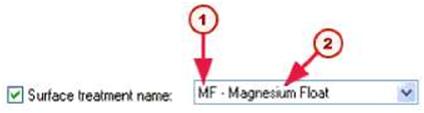
| In this example: • 1 is the surface treatment type (concrete finish) • MF is the code for the surface treatment option • “Magnesium Float” is the full name of the surface treatment option (remember to enclose the name in double quotes ” “) Here is how this option appears in the dialog box: |
|||||||
 |
|||||||
| © © | Code | ||||||
| Full name | |||||||
| Adding surface treatment information to report templates You can include the following surface treatment specific fields in report templates: |
|||||||
| TEKLA STRUCTURES 14.0 Parts | 101 | ||||||
|
||||||||||||||||||||||||||||||||||||||||||||||||||
 |
||||||||||||||||||||||||||||||||||||||||||||||||||