

 |
|||||
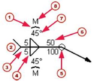
| m) Site weld f2J Pitch (c-to-c spacing) f3J Lenght C4) Stitch weld |
|||||
| ?/ | |||||
| 12IS1V | \ | ||||
| m) Effective throat f2J Root opening | |||||
| Reference line and arrow Arrow and other side |
The weld symbol also contains a reference line and an arrow. The arrow connects the reference line to the arrow side of a connection. When parts are welded together, you can place welds on: • The arrow sides only • The other sides only • Both the arrow and other sides The welds on the arrow and other sides of a part can have different weld properties. By default, the properties you define for a weld on the arrow side appear above the reference line in drawings. The properties of an other-side weld appear below the reference line in the weld symbol. |
||||
 |
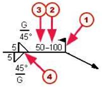
To show the arrow-side weld properties below the reference line in a weld symbol and the other-side properties above, use the variable XS_AISC_WELD_MARK. | ||||
| 114 TEKLA STRUCTURES 14.0 Detailing | |||||
|
||||||||||||||||||||||||||||||||||||||||||||||||||||||||||||||||||||||||||||||||||||||||||||||||||||||||||||||||||||||||||||||||||||||||||||
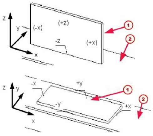
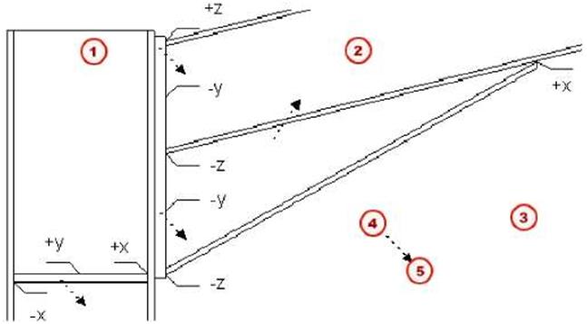
| Weld position You define the position of a weld relative to the work plane. The type and position of the parts to be welded affect the position of the weld. The options for weld position are: • x • y |
||||||||||||||||||||||||||||||||||||||||||||||||||||||||||||||||||||||||||||||||||||||||||||||||||||||||||||||||||||||||||||||||||||||||||||
| TEKLA STRUCTURES 14.0 117 Detailing | ||||||||||||||||||||||||||||||||||||||||||||||||||||||||||||||||||||||||||||||||||||||||||||||||||||||||||||||||||||||||||||||||||||||||||||
| z | ||
| These can all be in a positive or negative direction. Tekla Structures creates the weld on the face or side of the part that faces in the selected direction (x, y, or z). See the illustrations below: |
||
 |
||
| Mj Secondary part f2J Main part | ||
| If there are no faces that touch in the specified direction, Tekla Structures places the weld relative to the center point of the secondary part. | ||
 |
||
| MJ Assembly main part (2J Assembly main part f3J Welding order t4j secondary fs) primary |
||||
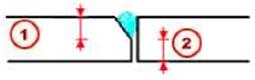
| Weld preparation | ||||
| When preparing welds, Tekla Structures bevels the parts to be welded using an anti-material cutting part. Tekla Structures subsequently deletes this cutting part. Tekla Structures displays weld preparations using cyan dash-and-dot lines. Some weld types and connections also automatically prepare the parts to be welded. | ||||
 |
||||
| To prevent automatic weld preparation, set the variable XS_DISABLE_WELD_PREP_SOLID=TRUE. | ||||
| VV1 | ||||
| 4.3 Fine-tuning part shape | ||||
| Introduction | This section describes the various tools you can use to fine-tune the shape of a part. | |||
| 9 | ||||
| Chamfer | |||
| Some part corners can be chamfered. You can use the Chamfer command to shape the following parts: polybeam, contour plate, strip footing, concrete polybeam, concrete slab, and concrete panel. Tekla Structures creates chamfers using the current properties in the Chamfer Properties dialog box. Click Detailing > Properties > Chamfer… to open the dialog box, or double-click an existing chamfer. |
|||
 |
|||
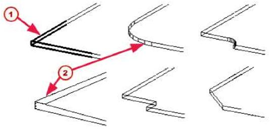
| fl) Default chamfer f2J Modified chamfers | |||
| When Tekla Structures creates a part, by default it has a rectangular chamfer at each corner, which does not change the geometry of the part. To change the shape of a part corner: 1. Set the chamfer properties. 2. Click Detailing > Create Chamfer. 3. Pick the corner(s) of the part to be chamfered. See the online help for more information on using this command. |
|||
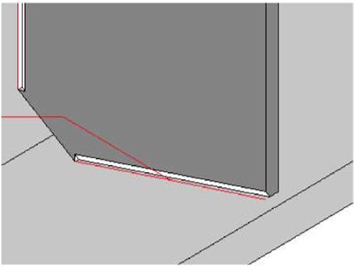
| Fitting | |||
| Use the Fitting command to fit the part end to a picked plane. You can use fitting to make part shorter, for example. | |||
 |
We recommend to move part Handles (p. 130) to make the part longer. | ||
 |
||||
| Mj Fitting symbol | ||||
| This command adjusts the end of a beam on a plane, perpendicular to the view plane, which passes through the cutting line you pick. Tekla Structures displays the fitting in the model using a blue fitting symbol. This command has no effect on contour plates. | ||||
| Cuts | ||||
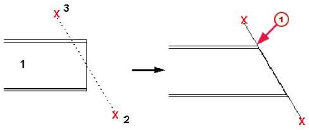
| Line cut | Use cut to shape parts. Cut is not meant for cutting the entire part end. Either move part Handle or use the Fitting command instead. You can create the following types of cuts for a part: • Line cut • Polygon cut • Part cut A line cut shapes end of the beam or column. Line cut cuts the end of a beam on a plane, perpendicular to the view plane, which passes through the cutting line you pick. Tekla Structures displays the cut in the model using a blue cut symbol. |
|||
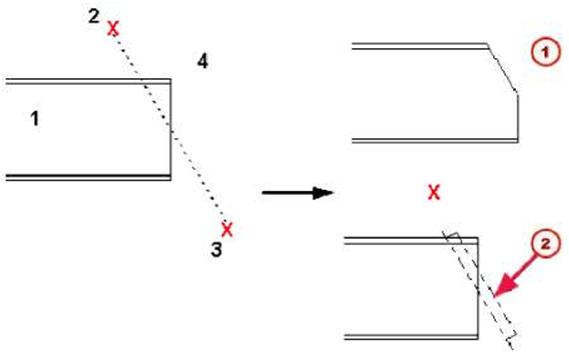 |
||||
| 121 | ||||
| Mj Exact representation (without symbol) (2J Fast representation (Cut symbol) | ||||
| Polygon cut | By default, line cuts do not affect beam length in NC files. To change this, see Fittings affect NC datathe online help. See the online help for more detailed information on using this command. This command cuts a part using a polygon. Tekla Structures displays the cut using dot-dash lines. You must create cuts in a plane view. |
|||
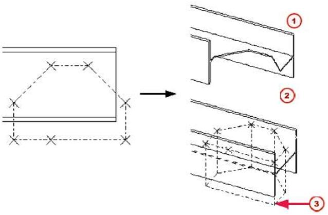 |
||||
| MJ Exact representation (without symbol) f2J Fast representation f3J Polygon-shaped cut | ||||
 |
You should always define the polygon so that there is some tolerance between the edges. If the edge of a cutting polygon is in exactly the same position as the edge of the part to be cut, it can be unclear whether the edge should be cut away. | |||
| Part cut | See online help for more detailed information on using this command. This command creates an anti-material cutting part. Tekla Structures does not delete the original cutting part. An anti-material part only cuts the selected main part. Tekla Structures displays the anti-material part using dot-dash lines. You can cut parts that already have cuts. For example, you can cut anti-material parts to create more sophisticated cut shapes. |
|||
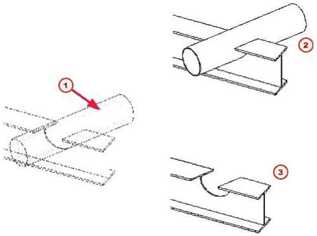 |
|||
| MJ Cut symbol (2J Hidden lines f3J Hidden lines (cutting part deleted) |
|||
 |
Do not create cuts with the same planes or vertices. This makes it unclear what should be cut away. | ||
| See online help for more detailed information on using this command. | |||
| Polygon shape | |||
| You can modify the shape of a polygonal part using the Detailing > Modify Polygon Shape command. You can use this command on the following parts: • polybeam • contour plate • strip footing • concrete polybeam • concrete slab • concrete panel |
|||
| See the online help for more information on using this command. | ||||
| 4.4 Detailing commands | ||||
| To fine-tune or detail your model, use the icons on the Detailing and Steel toolbars, or select commands from the Detailing menu. The following table lists the commands for detailing and gives a short description of each one. | ||||
| Detailing command | Icon | Description | ||
| Create Bolts | EMfc3 | Creates a bolt group in a part/parts. | ||
| Edit Bolted Parts |  |
Changes the parts a bolt group connects. | ||
| Create Weld between Parts | Creates a weld between two parts. | |||
| Create Polygon Weld |  |
Welds parts together using a polygon. | ||
| Create Weld to Part | Creates a weld to a part without connecting any other parts. | |||
| Prepare Part for Welding | m | Prepares the parts to be welded. | ||
| Create Chamfer |  |
Chamfers part corners. | ||
| Fit Part End | Creates a fitting to a part. | |||
| Cut Part > With Line |  |
Cuts the end of a beam on a plane, perpendicular to the work plane, which passes through the picked line. | ||
| Cut Part > With Polygon | A | Cuts a part using a polygon. | ||
| Cut Part > With Another Part |  |
Cuts a part with another part. | ||
| Modify Polygon Shape | m | Modifies the shape of a polygonal part. | ||