
|
Planning the Frame An experienced carpenter can frame a simple building from the most minimal drawings, but the framing for a larger or custom-designed structure may need to be planned as carefully as for a steel- or concrete-framed building (Figure 5.16). The architect or engineer determines an ef cient layout and the appropriate sizes for joists and rafters, and communicates this information to the carpenters by means of framing plans (Figures 5.17 and 5.51). For most purposes, member sizes can be determined using standardized structural tables that are part of residential building codes, or, for more complex framing or special be required. Larger-scale section details, similar to those seen throughout this chapter, are prepared for major connections in the building system. The architectural fl oor plans serve to indicate the locations and dimensions
Figure 5.17 A framing plan for the ground-fl oor platform of the building shown in Figure 5.19. of walls, partitions, and openings, and the exterior elevations show the outside faces of the building, with vertical dimensions or elevations indicated as required. For most buildings, building sections are also drawn that cut completely through the building, showing the dimensional relationships of the various ß oor levels and roof planes and the slopes of the roof surfaces. Interior elevations are often prepared for kitchens, bathrooms, and other rooms with elaborate interior features.
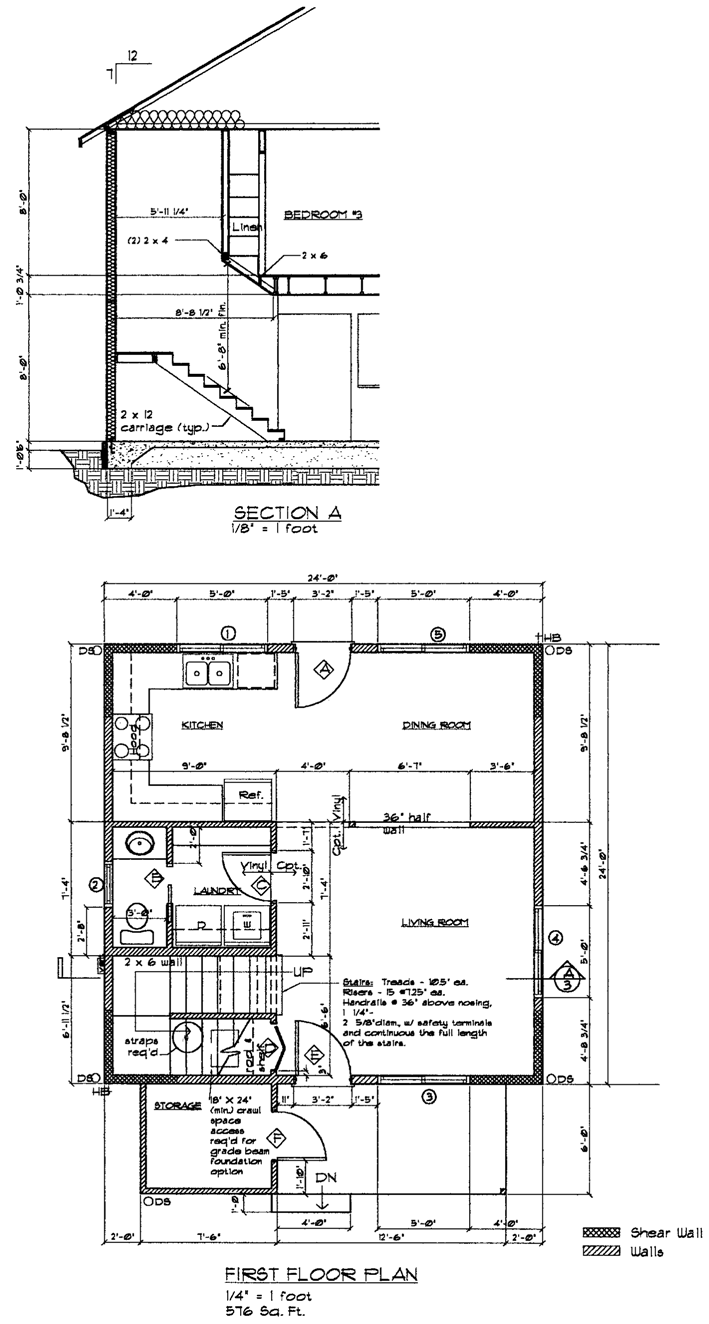
Figure 5.16 A fl oor plan and building section are two important components of the construction drawings for a simple house with wood light framing. The ground fl oor is a concrete slab on grade. Notice that portions of the walls have been designated on the fl oor plan as shear walls; shear walls are discussed beginning on page 185. |
|
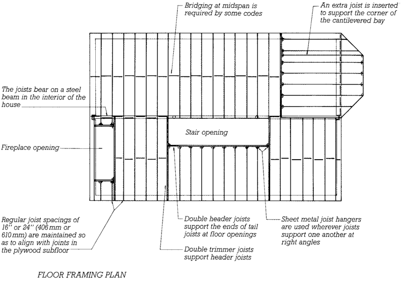
Figure 5.17
A framing plan for the ground-fl oor platform
of the building shown in Figure 5.19.
Erecting the Frame
The erection of a typical platform frame (referred to, imprecisely, asrough carpentry in the architects specications) can best be understood by following this chapters sequentialisometric diagrams, beginning with Figure 5.19. Notice the basic simplicity of the building process: A platform is built on top of the foundation.Walls are assembled horizontally on
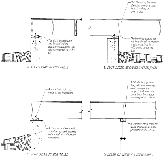
Figure 5.18
Ground-fl oor framing details, keyed to the lettered circles in Figure 5.19. A
compressible or resilient sill sealer strip should be installed between the sill and the
top of the foundation to reduce air leakage but is not shown on these diagrams. Using
accepted architectural drafting conventions, continuous pieces of lumber are drawn
with an X inside and intermittent blocking with a single diagonal. The metal termite
shield in detail C is used in areas where the risk of termite infestation is high. It
prevents subterranean termites from traveling undetected from cracks in the concrete
into the wood framing above.