

| 8.1 GENERAL INFORMATION | |||
|
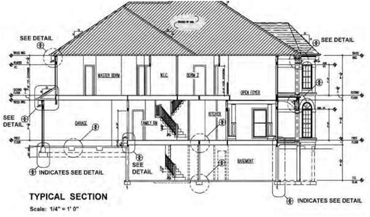
Blueprint drawings—as applied to the building-construction industry—are generally used to show how a building, object, or system is to be constructed, implemented, modified, or repaired. One of the main functions of graphic symbols on construction drawings is to reference other drawings within the set. For example, a circle drawn around an area of a drawing with an extension to a number would indicate that this portion of the drawing has been drawn to a larger scale to provide more information than would be possible at the existing scale (Figure 8.1). In the preparation of working drawings for the building-construction industry, architects and engineers have devised systems of abbreviations, symbols, and keynotes to simplify the work of those preparing the drawings and to keep the size and bulk of the construction documents to an acceptable, comprehensible minimum. Drawing simple building components without the use of symbols would indeed be a tiresome task. Visualizing and reading construction drawings therefore necessitate a knowledge of symbols and abbreviations used in the construction industry and of their proper use in representing materials and other components and their locations (Figure 8.2). Symbols may vary slightly from one locale to another. The majority of architects and engineers today use symbols adopted by the American Institute of Architects (AIA) and the American National Standards Institute (ANSI). However, designers and drafters continue to modify some of these symbols to suit their own particular needs for the types of projects they are normally commissioned to design. For this reason, most drawings have a symbol list or legend drawn and lettered either on each set of working drawings or in the written specifications. Modified symbols are normally selected by the consultant because they are easier to draw and interpret and are sufficient for most applications. In order for this system of symbols to work, each drawing within the set has its own unique number. This is usually a combination of numbers: the number for the individual drawing as well as the page or sheet number on which the specific drawing appears. Individual drawings may be referenced many times throughout a set of construction drawings. The symbols discussed in this chapter are not all-inclusive by any means, but they are the ones that the builder or designer is likely to encounter in most general building-construction applications. |
|||
| Copyright © 2009 by The McGraw-Hill Companies, Inc. | 195 | ||
| 196 | Chapter 8 | ||
 |
|||
| Figure 8.1 A computer-generated section of a residential structure showing different elements with encircled portions. These portions are detailed to a larger scale at another location within the set. Notice that the highlighted portions do not necessarily have to be circles but can take on other shapes. | |||
|
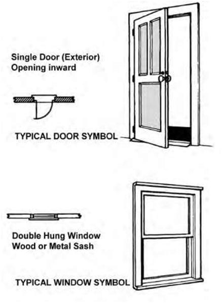
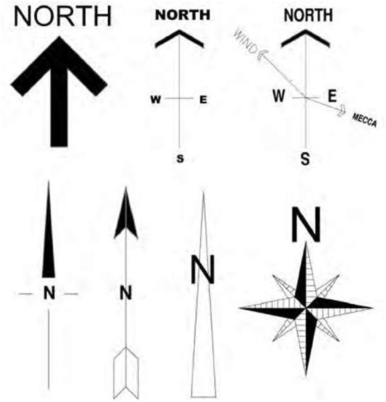
Graphic symbols are often used on building plans to show elements such as gas and water service lines and window types as well as to list drawing notes and identify finishes and revisions. The same graphic can be used for more than one purpose. For example, the same symbol is used for every revision; it is the number within the graphic that carries specific information. Trade-specific symbols are included for the electrical, HVAC, and plumbing trades. One of the most important symbols to use right at the beginning of a new job is the directional symbol. This symbol, which is usually an arrow labeled “N” for north, enables the reader of a construction drawing to orient it. However, there are numerous variations of the “North” point symbol, depending on the designer’s fancy (Figure 8.2). Whichever symbol is decided upon, a drawing is properly oriented when it is held so that the north arrow shown on the drawing is pointing toward north. The drawing must be properly oriented so the reader can relate the information on it to the surrounding area. |
|||
| The Meaning of Symbols | 197 | ||
 |
|||
| Figure 8.2 Examples of typical door and window symbols shown in both plan (as it may appear on a blueprint) and in pictorial form. Reading working drawings necessitates the ability to read, and understand and visualize the various symbols. | |||
|
The following figures show some of the most common standard symbols; during the course of your work you will likely see many other types as well. For various reasons, some of the symbols on a drawing may not be standard. Many times you will figure out what a symbol means by analyzing it and thinking about what it looks like. The legend on a drawing should show any nonstandard symbols and their meanings. Occasionally a symbol for a particular component or device may have been specifically created by the architect or engineer who developed the drawing. |
|||
| 198 | Chapter 8 | ||
 |
|||
| Figure 8.3 Different examples of north-point symbols. Architects and designers often like to design their own symbols for particular items. | |||
| 8.2 ARCHITECTURAL GRAPHIC SYMBOLS | |||
|
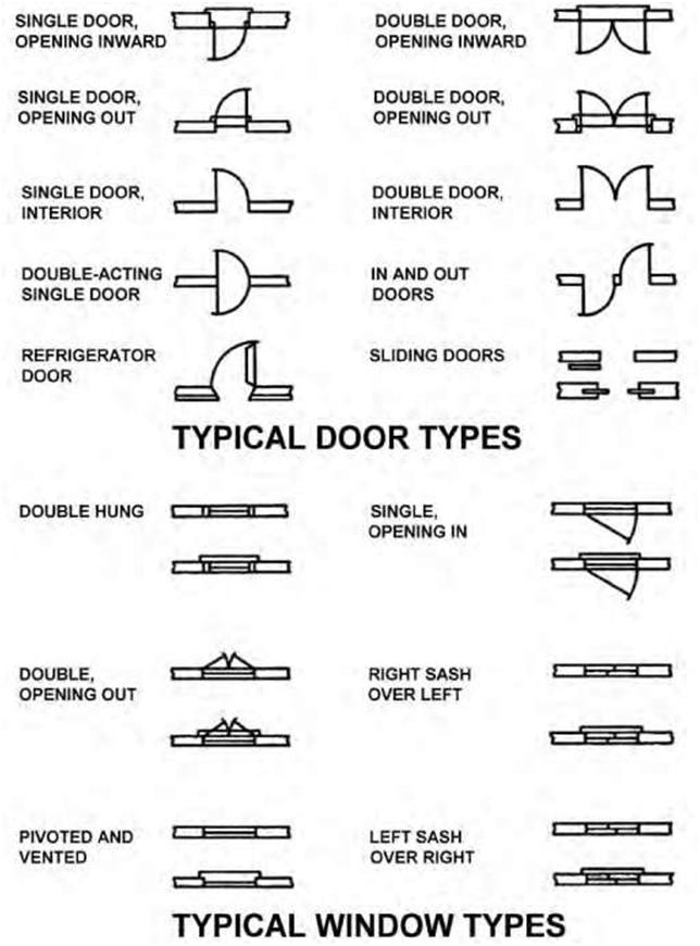
Reading blueprints requires a good understanding of line types. For example, on a plot plan some of the information shown will include property lines, rights-of-way, easements, topographic features, and a north arrow. Line types are discussed in greater detail in Chapter 3. Figure 8.4A and B show various door, window, and wall symbols used in general construction. |
|||
| The Meaning of Symbols | 199 | ||
 |
|||
| Figure 8.4A Examples of different common door and window symbols shown in plan form. | |||
| 200 | Chapter 8 | ||
 |
|||
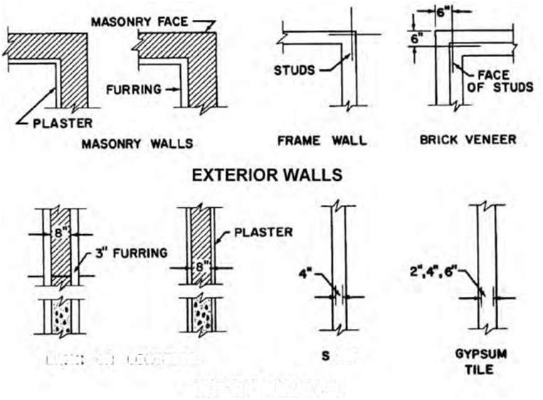
| INTERIOR WALLS Figure 8.4B Examples of different exterior and interior wall symbols used in general construction. |
|||
| 8.3 MATERIAL SYMBOLS | |||
|
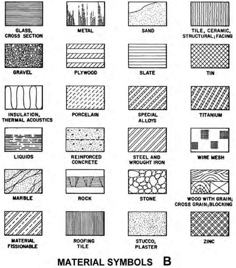
Material symbols are used to represent materials or contents on floor plans, elevations, and detail drawings. Different symbols may be used to represent the same item on these drawings. The outline of the drawing may be filled in with a material symbol to show what the object is made of. Many materials are represented by one symbol in elevation and another symbol in section. Examples of this are concrete block and brick. Other materials look pretty much the same when viewed from any direction, so their symbols are drawn the same in sections and elevations as seen in Figure 8.5. |
|||
| The Meaning of Symbols | 201 | ||
 |
|||
| Figure 8.5 Examples of graphic symbols of materials used by architects and engineers when preparing blueprints. | |||
| 202 | Chapter 8 | ||
 |
|||
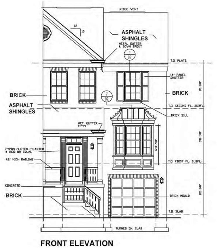
| Figure 8.6 Drawing of a part elevation of a townhouse showing the use of notes for the brick on the facade and asphalt roof shingles rather than partial drawing of the symbols. | |||
| The Meaning of Symbols | 203 | ||
|
When a large area is made up of one material, it is common to only draw the symbol in a part of the area. Some drafters simplify this even further by using a note to indicate what material is used and omitting the symbol altogether (Figure 8.6). Throughout the remainder of this text, material symbols are presented as they appear in plan and elevation views. Many symbols are designed to approximate the actual appearance of material. This is especially true on elevation drawings, as shown in Figure 8.6. Because of the complexity and space required, many symbols do not have any graphic relationship to the items they represent. These must be memorized if drawings are to be consistently interpreted. When material symbols are similar, always look for a notation, different view, detail, or specification for information about the material. 8.4 ELECTRICAL SYMBOLS |
|||
|
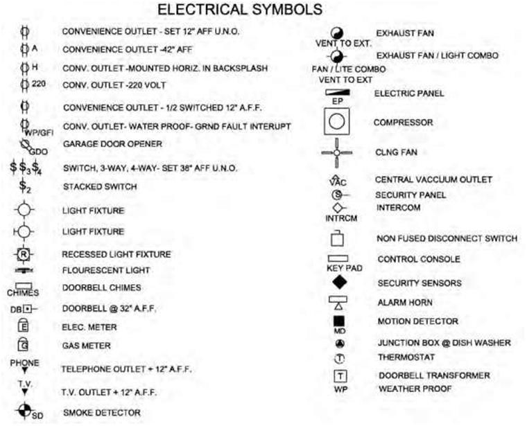
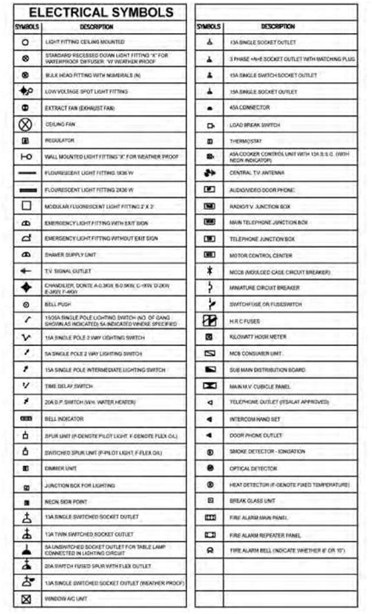
Electrical drawings—like other types of building-construction drawings—must be prepared by competent electrical drafters in a given time period to avoid unnecessary delays. Symbols are used on electrical drawings to simplify the drafting work for both the drafters and the workers interpreting the drawings. It should be noted that electrical symbols are not standardized throughout the industry, which is one reason why electrical drawings typically have a symbol legend or list. Many electrical symbols are used to show the desired lighting arrangement. Switch symbols are usually placed perpendicular to the wall and read from the right side or bottom of the sheet. Figure 8.7 shows two lists of electrical symbols currently in use on most electrical drawings. The lists represent a good set of electrical symbols in that they are easy to draw, easily interpreted by workers, and sufficient for most applications. The electrical system for a small property would typically include wiring as well as devices such as switches, receptacles, light fixtures, and appliances. Wiring is indicated by lines that show how devices are connected. These lines are not shown in their actual position. They simply indicate which switches control which lights. Outlets (receptacles) and switches are usually shown in their approximate positions. Major fixtures and appliances are shown in their actual positions. In Figures 8.8, 8.9, and 8.10 we see examples of receptacle symbols, alarm symbols, and other electric symbols. Some of the symbols listed contain abbreviations, such as TV for television outlet and WP for weatherproof. Others are simplified pictographs, such as the symbol for an electric meter. One way to develop the ability to interpret a drawing and its symbols is by first learning the basic form of the different symbols. This is because many symbols are similar (square, circle, etc.), and the addition of a line, letter, or number determines the specific meaning of that symbol. 8.5 PLUMBING SYMBOLS |
|||
|
One must differentiate between industrial and residential or commercial piping. Industrial piping is generally designed to carry liquids and gases used in manufacturing processes. In heavy construction steel pipes have welded or threaded fittings and connections. Piping used in commercial and residential applications is generally termed “plumbing” and is designed to carry fresh water, liquid and solid wastes, and gas. These pipes can be made of plastic, copper, galvanized steel, or cast iron. In preparing a plumbing drawing, all pipe fittings, fixtures, valves, and other components are represented by symbols |
|||
| 204 | Chapter 8 | ||
 |
|||
| Figure 8.7 List of general electrical symbols in current use. | |||
| such as those listed in Figures 8.11A,B,C The use of these symbols simplifies considerably the preparation of piping drawings and conserves a considerable amount of time and effort. In residential applications, plumbing information can often be provided on the floor plans in the form of symbols for fixtures and notes (for pipe sizes, slope, etc.) for clarification. Other plumbing items and information to be shown on the floor plans include water connections, floor drains, vent pipes, and sewer connections. Floor drains are shown in the approximate location on the plans and sections, with notes indicating the size, type, and slope to drain. Sewer and water-service lines are located in the position in which these utilities enter the building. Service lines are normally indicated on the site plan. Vent pipes |
|||
| The Meaning of Symbols | 205 | ||
 |
|||
| Figure 8.8 List of common receptacle symbols often found on blueprints. | |||
| 206 | Chapter 8 | ||
| SYMBOLS – FIRE ALARM SYSTEM | |||
| 0 | DESCRIPTION SMOKE DETECTOR DUCT TYPE. VALVE SUPERVISORY SWITCH, ELECTROMAGNETIC TYPE DOOR HOLDER OUTLET. FIRE ALARM TERMINAL CASINET. POST INDICATOR VALVE. FIRE ALARM TRANSMITTER (BASE LOOP) NUMERALS DENOTE CODE, FIRE ALARM TROUBLE TRANSMITTER (BASE LOOP) NUMERALS DENOTE CODE. CITY FIRE ALARM MASTER STATION MTD 5′-6″ [1676mm] AFF UNLESS NOTED. FIRE ALARM RECORDER. FIRE ALARM BATTERIES BATTERY CHANGER, FIRE ALARM CENTRAL CONSOLE, |
||
| ©Z-4-6 | |||
| Figure 8.9 List of fire-alarm-system symbols in current use. | |||
 |
|||
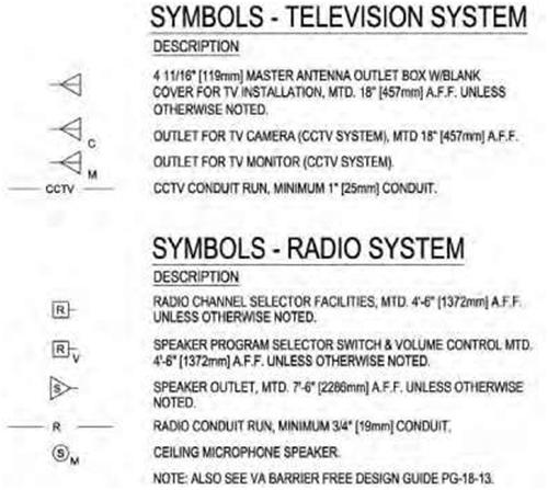
| Figure 8.10 Symbols for typical television and radio systems. | |||
| The Meaning of Symbols | 207 | ||
 |
|||
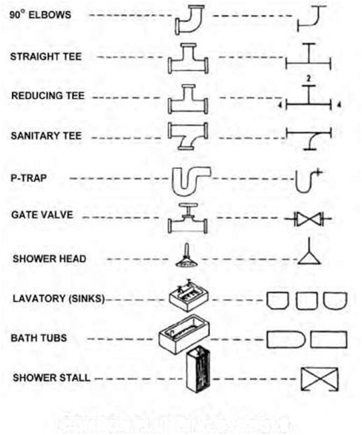
| COMMON PLUMBING SYMBOLS Figure 8.11A Examples of common plumbing fittings and symbols. |
|||
| (which allow for a continuous flow of air through the building) are drawn in the wall according to their location on the plan, with a note indicating the material and size. When plumbing drawings are prepared, they are not usually shown on the same sheet as the architectural floor plan. The main plumbing items shown on the floor plans are the fixtures. Drainage, vent, and water systems are drawn with thick lines using symbols, abbreviations, and notes. |
|||
| 208 | Chapter 8 | ||
 |
|||
| HOW TO READ PLUMBING FITTINGS Figure 8.11B Examples of different types of plumbing connections. |
|||
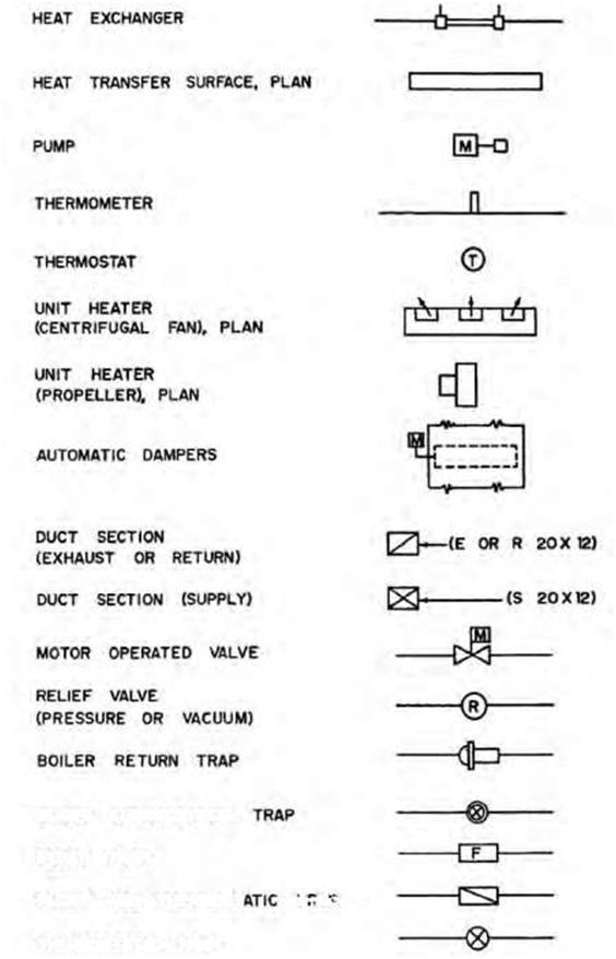
| 8.6 HEATING, VENTILATION, AND AIR-CONDITIONING SYMBOLS | |||
|
The main function of HVAC drawings is to show the location of the heating, cooling, and air-conditioning units as well as the piping and ducting diagrams. Graphical symbols on HVAC drawings are similar in pattern to those used for plumbing. In Figures 8.12A and B we see examples of typical HVAC symbols in current use in the United States and Europe. It should be noted that on some HVAC drawings one sees two types of symbols. The main duct may consist of a rectangle to represent the actual size of the ductwork—including reductions. However, the |
|||
| The Meaning of Symbols | 209 | ||
 |
|||
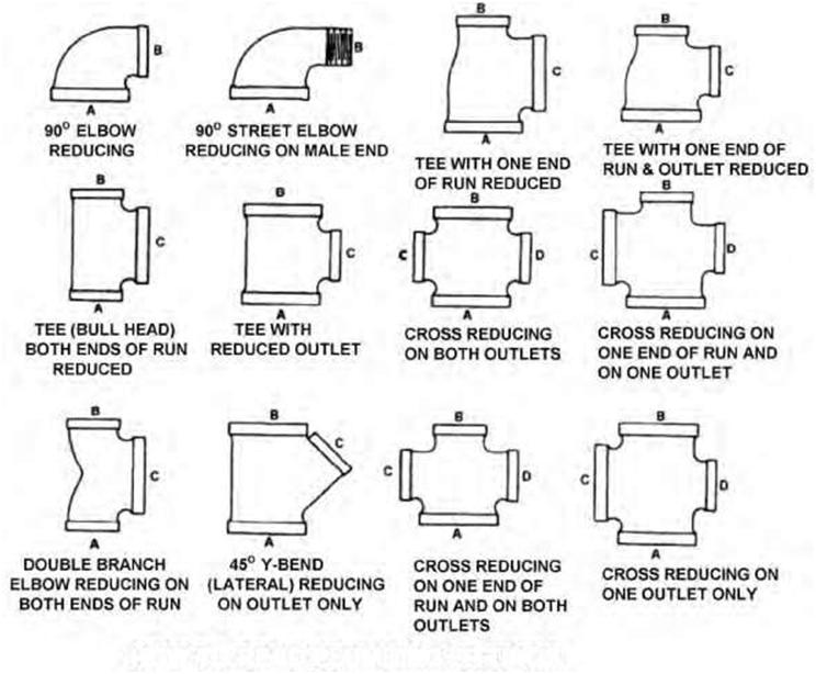
| Figure 8.11C Examples of typical pipe fitting symbols showing sample applications and pictorial representations of the fitting. | |||
| 210 | Chapter 8 | ||
 |
|||
| AIR-CONDITIONING SYMBOLS Figure 8.12A Common air conditioning symbols in general use. |
|||
| The Meaning of Symbols | 211 | ||
 |
|||
| BLAST THERMOSTATIC FLOAT TRAP FLOAT AND THERMOST T-:A:’- THERMOSTATIC TRAP Figure 8.12B Examples of heating symbols in general use. |
|||
| 212 | Chapter 8 | ||
|
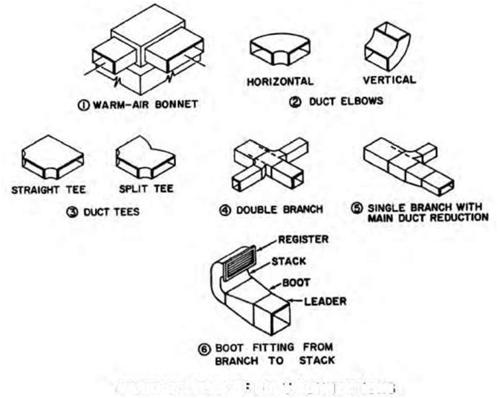
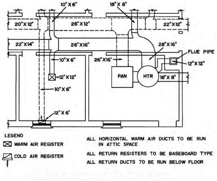
branches are shown by a single line with the dimensions of each noted adjacent to the lines. Both methods are used on HVAC drawings throughout the building-construction industry, either singly or in combination (Figure 8.13A and B). A number of custom HVAC CADD programs are currently available to help improve drafting productivity and efficiency. 8.7 MISCELLANEOUS SYMBOLS |
|||
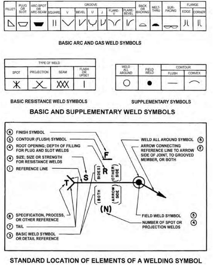
| Component Symbols Component symbols represent such items as furniture, fixtures, and appliances. Many component symbols are similar to the actual item represented in plan/elevation view. Specialist Symbols There are many specialist trades, such as welding, that have their own specific symbols. Figure 8.14 shows examples of basic and supplementary weld symbols and the standard location of elements of a welding symbol. Figure 8.15 and Figure 8.16 are further examples of specialist type symbols. Indexing Symbols To summarize, when reading symbols on a blueprint, the following should be remembered: Placement of symbols on floor plans and elevations may be approximate unless they are dimensioned. Do not scale a symbol to determine its size. Specific information should be obtained from relevant details, schedules, or specifications. A symbol’s size may vary according to the scale of the drawing. Symbols drawn to represent surface materials may cover only a representative portion of an area. Abbreviations are often used in place of a graphic symbol in order to reduce drawing time and space. A list of architectural/construction abbreviations is given in the Appendix. Symbols for the same items are usually different in plan, elevation, and section drawings. Some symbols may use the same or similar graphic treatments in elevation. Check notations, detail drawings, and specifications for identification. |
|||
| The Meaning of Symbols | 213 | ||
 |
|||
| VARIOUS TYPES OF DUCT CONNECTIONS Figure 8.13A Various types of duct connections. | |||
| 214 | Chapter 8 | ||
 |
|||
| TYPICAL WARM-AIR HEATING SYSTEM PLAN Figure 8.13B A typical warm-air heating plan. |
|||
| The Meaning of Symbols | 215 | ||
 |
|||
| Figure 8.14 Diagram showing basic and supplementary weld symbols and the standard location of elements of a welding symbol. | |||
| 216 | Chapter 8 | ||
 |
|||
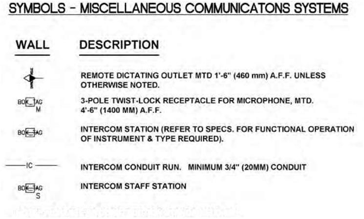
| NOTE: ALSO SEE VA CONSTRUCTION STANDARD CD-2B. Figure 8.15 Examples of symbols used in miscellaneous communications systems. | |||
| The Meaning of Symbols | 217 | ||
| SYMBOLS-SITE WORK DESCRIPTION DIRECT BURIAL CABLE – SIZE AS INDICATED. TELECOMMUNICATIONS DUCT POWER DUCT EXTERIOR FLOOD LIGHT DUAL POWER & TELECOMMUNICATIONS MANHOLE PADMOUNT TRANSFORMER – NUMERAL INDICATES KVA SIZE SWITCHGEAR – SUBSCRIPT DENOTES SUBSTATION HIGH-VOLTAGE SWITCH ON CONCRETE PAD LOW-VOLTAGE SWITCH ON CONCRETE PAD SWITCHBOARD |
|||
| SYMBOLS – REWIRING AND DEMOLITION DESCRIPTION EXISTING FAN – REMOVE FAN AND BLANK OUTLET EXISTING CONDUIT IN PLACE – REMOVE EXISTING WIRES AND INSTALL NEW WIRES AS INDICATED EXISTING CONDUIT AND WIRE TO REMAIN EXISTING CONDUIT AND WIRE TO BE ABANDONED OR REMOVED CONNECTION OF NEW CONDUIT TO EXISTING CONDUIT W/APPROVED TYPE COUPLINGS – INSTALL NEW WIRES CONDUIT SEAL FOR EXPLOSION PROOF INSTALLATION PLACED ADJACENT TO DEVICE SYMBOL DENOTES EQUIPMENT SHALL BE REMOVED AND OUTLET BLANKED PLACE ADJACENT TO DEVICE SYMBOL DENOTES EQUIPMENT SHALL BE REMOVED |
|||
Could you tell me which standard you have referred for these symbols.
I like it very much!
thanks for this post, really helpful
Electric contract Sec 81 all lighting project workings
What is “PPT” symbol on electricity wiring chart mean?
What is a triangle like data symbol but is connect with 2 boxes with one capital F in both boxes
I do not understand the symbols
Thank you sir is helpful and learnable I will copy it down sir
english? do you know how to write? white boy
Thank you 😊