
Sills on Foundation Walls
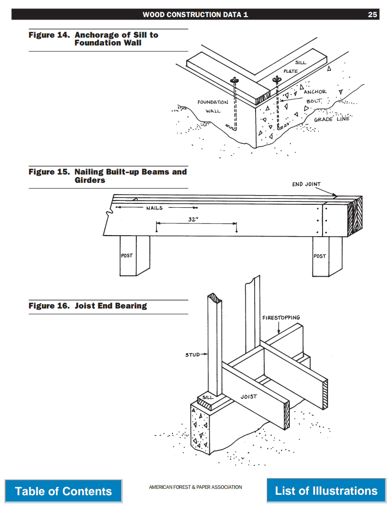
Sills resting on continuous masonry foundation walls are generally of nominal 2×4 or 2×6 lumber. They are an- chored to masonry walls with ½-inch bolts at approximately 6-foot intervals. Bolts are embedded at least 6 inches in poured concrete walls and at least 15 inches in masonry block walls, Figure 14. Metal anchor straps, embedded in foundation walls at sufficient intervals to permit adequate nail fastening to sills, may also be used.
Foundation Wall
Sills on Piers
Sills supported by free-standing piers must be of ad-equate size to carry all imposed loads between piers. They may be of solid wood or of built-up construction such as
described for beams and girders. Sills are anchored to piers with ½-inch bolts embedded at least 6 inches in poured concrete and at least 15 inches in masonry block, Figure 8.
Beams and Girders
Beams and girders are of solid timber or built-up con- struction in which multiple pieces of nominal 2-inch thick lumber are nailed together with the wide faces vertical.
Such pieces are nailed with two rows of 20d nails-one row near the top edge and the other near the bottom edge. Nails in each row are spaced 32 inches apart. End joints
of the nailed lumber should occur over the supporting column or pier. End joints in adjacent pieces should be at least 16 inches apart, Figure 15. Glued-laminated mem-
bers are also used. Beams and girders that are not continuous are tied together across supports. Bearing of at least 4 inches is required at supports.
Selection and Placing of Joists
Span Tables for Joists and Rafters (Appendix, Item 4) published by the American Forest & Paper Association,
provides maximum allowable spans for the different spe-cies and grades of lumber depending upon floor and roof design loads and spacing of the members.
Joist end-bearing should not be less than 1½ inches on wood or metal and 3 inches on masonry. Joists are usu-ally attached to sills by two toe-nails, or by metal framing
anchors, Figures 8, 11 and 16. Joists should be placed so the top edge provides an even plane for the sub-floor and finished floor. It is preferable to frame joists into the sides
of girders to reduce the cumulative effect of seasoning shrinkage, Figures 17, 18, 19 and 20.
Bridging
Adequately nailed subflooring will maintain the up- per edges of floor joists in proper alignment. Nailing the ends of joists to band joists or headers, Figures 11 and 24, provides additional joist support that, under normal conditions, eliminates the need for intermediate bridging. Where the nominal depth-to-thickness ratio of joists ex-ceeds 6, or where builders have encountered problems with twisting of joists in service, intermediate joist bridg-ing is installed at 8-foot intervals. Bridging may also be accomplished with cross braces of nominal 1×4-inch lumber or solid 2-inch lumber, Figures 21 and 22.
Framing of Floor Openings
Headers, trimmers and tail joists form the framing for floor openings. Trimmers and headers are doubled when
the header span exceeds 4 feet. Headers more than 6 feet in length are supported at the ends by joist hangers or
framing anchors unless they are bearing on a partition, beam or wall. Tail joists which exceed 12 feet in length
are supported on framing anchors or on ledger strips not less than nominal 2×2 inches, Figures 23, 24 and 25.
Notching and Boring of Joists
Notches or holes in joists for plumbing or wiring shall not be cut in the middle one-third of the joist span. Notches in the outer-third sections of the span may be no greater than one-sixth the joist depth. Where notches are made at the joist ends for ledger support, they may be no greater than one-fourth the joist depth. Holes in the joist are are limited in diameter to one-third the joist depth and are cut with the edge of the hole no closer than 2 inches to
the top or bottom edges, Figure 26.
Support of Partitions
Bearing partitions are normally placed over girders or walls which support the floor system. Where floor fram- ing is adequate to support the added load, bearing partitions may be offset from supporting members by no more than the joist depth, unless floor joists are designed to carry the increased load, Figures 27 and 28. Where non-bearing partitions run parallel to floor joists, the joist under the partition is doubled to support increased loads which frequently occur adjacent to the partition, Figures 29 and 30.
Overhang of Floors
Where second-floor joists project over the first story wall at right angles, they are cantilevered to support the second story wall, Figure 35. Where the overhanging wall is parallel to the second floor joists, a double joist sup- ports lookout joists which extend at right angles over the first story wall, Figure 36. The double joist is located inside the supporting wall at a distance equal to twice the overhang. Lookout joists are framed into the double joist
by framing anchors or a ledger strip nailed at the upper edge.

Second Floor Overhang of Exterior Wall, Joists at Right Angles to Supporting Walls
. Second Floor Overhang of Exterior Wall, Joists Parallel to Supporting Walls

Attachment of Non-Bearing Partition to Ceiling Framing
Stairway Framing

Framing Over Bearing Partition, Balloon Construction

Framing of Tail Joists by Framing Anchors
Framing of Header to Trimmer by Joist Hangers
Notching and Boring of Joists

Solid Bridging of Floor Joists

Joist Supported by Metal Framing Anchors
Joists Resting on Girder
Joists Resting on Steel Beam

Girder Framing in Exterior
Termite Shields