Tekla Structures – Basics

In this section            This section presents basic Tekla Structures vocabulary and concepts so that you can start modeling. The illustration below shows the modeling guides you use in Tekla Structures windows.


View m)    Points are red outside the view plane

\2J    Grid is on the view plane

f3j    Green dashed lines outline the work area

(4)    Points are yellow on the view plane

f5J    Arrow symbol indicates the work plane

Qej    The coordinates symbol indicates the direction of the model

To see your Tekla Structures model from virtually any angle, you can move and rotate the model. You can also create views. A view is a representation of a model from a specific location. Each view is displayed in its own window inside the Tekla Structures window.

The symbol with three axes (x, y, and z) represents the local coordinate system and indicates the direction of the model. It is located in the lower right corner of the model view. The coordinate symbol follows the work plane.

Coordinate system
The green cube in a wire frame view represents the global coordinate system and lies at the global point of origin.
 

Getting Started

Work plane The red coordinate arrow symbol indicates the work plane, which is the current local coordinate system of the model. The arrow symbol shows the xy plane. The z direction follows the right-hand rule. You can reset the work plane so as to ease modeling and placing objects. Most of the commands, which are dependent on the coordinate system, use work plane coordinates; e.g. creating points, part positioning, and copying always comply with the work plane coordinate system. The work plane is the same in all views.

Tekla Structures indicates the work area of a view using green, dashed lines. Defining the work area makes it faster and easier to work with the model. Objects outside the work area still exist, but they are not visible. So you can confine to a substructure, for example, and the views to the model are simpler and quickly updated.

Dash-and-dot lines show the projections of the grids which are visible on the view plane.

The appearance of points also shows which view plane you are using. Points located in the view plane are yellow. Points outside the view plane are red.

Work area
Grid and view plane
Opening a model
To open a Tekla Structures model:

1.     Click File > Open… or

You can only have one model open at a time. If you already have a model open, Tekla Structures prompts you to save that model.

2.     In the Open dialog box, select the model.

By default, Tekla Structures searches for models in the folder you specified when you installed Tekla Structures. If your model is in another folder, click Browse… to browse for the model folder, or use the Look in list box with the recently used folders.

3. Click OK to open the model.
45
If no views are visible after you have opened a model, Tekla Structures prompts you to select one.
You can also double-click a model on the list to open it, or use the Model name list box to open a recently used model.
. You can sort models by clicking the column titles.
When the models are sorted alphabetically by their names, you can use the keyboard to select models. For example, when you type N, Tekla Structures selects the first model starting with an N.

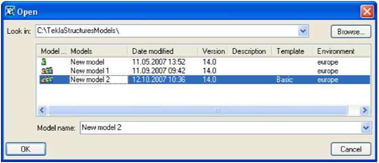
The Open dialog box provides you with the following information:

•      Whether the model was last saved in single-user 3 or multi-user ^fl mode (Model type)

•      The version of Tekla Structures the model was created or last saved in

•      Designer

•      Description

•      Template that was used as a basis when creating this model

•      Environment

The Designer and Description columns show information from the properties dialog box. Switching between single-user and multi-user modes

You can easily switch between single-user and multi-user modes by using the different options in the Open dialog box.

To open a multi-user model in single-user mode:

1.     In the Open dialog box, select the multi-user model.

2.     Right-click and select Open as single-user model from the pop-up menu.

To open a single-user model in multi-user mode:

1.     In the Open dialog box, select the single-user model.

2.     Right-click and select Open as multi-user model from the pop-up menu.

3.     Tekla Structures asks for the name of the server. In the Open as multi-user model dialog box, enter the server name or select it from the list box, and then click OK.

Changing the server To change the Tekla Structures server of a multi-user model:
1.     In the Open dialog box, select the multi-user model.

2.     Right-click and select Change server from the pop-up menu.

3.     Tekla Structures asks for the name of the new server. In the Change server dialog box, enter the server name or select it from the list box, and then click OK.

T If you change the server of a model, but the connection to the new server cannot be established, the old connection is restored.
Getting Started

The file .This_is_multiuser_model located in the model folder defines whether the model is a multi-user or a single-user model. The file includes also the name of the server. You can open the file using any standard text editor.

See also For more information on the multi-user mode, see Multi-user Mode.
Creating a new model
When you first open Tekla Structures, only some icons such as New and Open are active. To create a new Tekla Structures model:

1.     Click File > New… or |J—I . The New dialog box appears.

You can only have one model open at a time. If you already have a model open, Tekla Structures prompts you to save that model.

2.     In the New dialog box, define the folder to save the model in.

By default, Tekla Structures saves models in the folder you specified when you installed Tekla Structures. If you want to save the model in another folder, click Browse… to browse for the model folder, or use the Save in list box with the recently used folders.

For more information on how to change the default model folder, see XS_RUNPATH in the System Manual.

3.     Enter the model name.

4.     In the Model type list box, select either Single-user or Multi-user.

5.     If you select Multi-user, enter the server name, or select a recently used server from the Server name list box. See also Overview of the multi-user system in the System Manual.

6.     Click OK to create the new model. The remaining icons become active and the model name appears in the title bar of the Tekla Structures window.

Every model must have a unique name. Tekla Structures does not allow duplicate model names.

Do not use special characters ( / \ ; : | ) in model names.

You can use model templates as a basis when you create new models.

For more information on creating model templates, see the Tekla Structures 14.0 Administrator's Guide.

Project setup
Update the project information at the beginning of a project to make reports and drawings to display the correct information automatically.
Getting Started
To update the project information, click File > Project Properties…. The Project Properties dialog box appears. Tekla Structures displays this information in different reports and drawing titles.
*& The names in the image below refer to template fields, which you can use when designing your own reports and templates.
[Si, Project properties
Project number

Name

Builder

Object

Address

Designer

Start date

End date

Info 1

Info 2

0 Description (Sho

1212

0

Tekla Corporation

®

W

114 Town Park Lane

(!)

G)

04/03/2006

33

05/19/2006

“05

mi

User-defined attributes…
wn in Open dialog box)

——————–

I

OK Apply

Cancel

fl) PROJECT f2j PROJECT [3J BUJEDEE [4J PROJECT [5J ADDRES [6J DESIGNE f7J STARTE [8J ENDDA _NUMBER _NAME

_OBJECT S R

ATE TE

Getting Started
MM INFO1 Mo} INFO2
Before starting a new project, read also Using effectively in the online help.
Defining the work area and shifting the work plane
Work area You can define the work area to suit particular situations, for example, to concentrate on a particular area of the model. You can shrink and expand the work area by picking the corner points of the new work area, or size the work area to include selected parts, or all model objects. You can define the work area in a selected view, or in all visible views.

To define the work area, use a command from the View menu:

Command Icon Description
Fit Work Area Using Two Points

Sets the work area based on two corner points you pick on the view plane. The of the work area is the same as the view depth.

To Entire Model in All Views Fits the work area to include all model objects in all visible views.
To Entire Model in Selected Views Fits the work area to include all model objects in the selected views.
To Selected Parts in All Views Fits the work area to include the selected model objects in all views.
To Selected Parts in Selected Views & Fits the work area to include the selected model objects in the selected views.
Work plane                 The current work plane defines the local coordinate system of a Tekla Structures model. You

can set the work plane to any position by picking points, parallel to one of the global basic planes, or on a part or view plane. The current work plane is model-specific, so it relates to all views.

When modeling sloped parts, shifting the work plane helps you to place parts accurately.

To shift the work plane, use the icons on the View toolbar, or select a command from the View menu. The following table lists the commands for setting the work plane, and gives a short description of each one:

Command Icon Description
Parallel To XY(Z) Plane…

L.

Sets the work plane parallel to xy, xz, or yz plane.
Using One Point

u.

Sets the work plane according to one picked point.
Using Two Points

k

Sets the work plane according to two picked points.
Command Icon Description
Using Three Points Sets the work plane according to three picked points.
Parallel To View Plane If Sets the work plane to be equivalent to the view plane of a picked view.
To Part Front Plane Sets the work plane parallel to the front plane of a part.
To Part Top Plane D. Sets the work plane parallel to the top plane of a part.
To Part Back Plane Sets the work plane parallel to the back plane of a part.
To Part Bottom Plane & Sets the work plane parallel to the bottom plane of a part.
Saving a model and exiting Tekla Structures
y
Save as Autosave To save a model, click File > Save or

Click File > Save as… to save a model with a new name, or to give a new model a specific name.

Tekla Structures automatically saves the model at set intervals. To set the interval and define the location of autosave files, see Autosave in the online help.

Saving models differs in multi-user mode. See Multi-user mode in the online help.
Exit To exit Tekla Structures, close the Tekla Structures window, or click File > Exit. A confirmation dialog box appears and you can choose whether or not to save the model.

Leave a Comment

This site uses Akismet to reduce spam. Learn how your comment data is processed.