
|
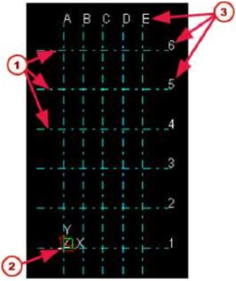
So that you can easily locate objects in your model, we strongly advise that you create a modular grid. The Tekla Structures grid is shown on the view plane by dash-and-dot lines. You can have more than one grid in a model. You may want to create a large-scale grid for the entire structure, and smaller grids for some detailed sections. Grids are rectangular. You can also create single grid lines and attach them to an existing grid. |
|||||||


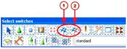


| Deleting grids and grid lines To delete a grid: 1. Ensure that the Select grids switch is selected. 2. Click any grid line, then right-click and select Delete from the pop-up menu. |
|||||
 |
When you delete a grid, ensure that you do not have any other object(s) selected. If you have also other objects selected, Tekla Structures only deletes the objects, not the grid. | ||||
| To delete a grid line: 1. Ensure that the he Select grid lines switch is selected. 2. Click the grid line you want to delete. 3. Right-click and select Delete from the pop-up menu. Introduction There are several ways to create views in Tekla Structures. For example, you can create views: • of the entire structure • of selected part(s) and component(s) • along the grid lines Each view has properties which define its appearance. You can change the appearance of a view after you create it so choose the creation method that suits you. This section describes the view-specific properties. You can open the view properties dialog box for each view, to view or modify the properties. |
|||||
| T | Unnamed views disappear when you close them. | ||||
|
You can have up to nine views on the screen at the same time. If you try to open more than nine views, Tekla Structures displays a warning. If the view does not appear, check how many views you have open. To switch between views, press Ctrl+Tab. |
|||||
| V | |||||
| Getting Started | |||||
| View plane | |||||
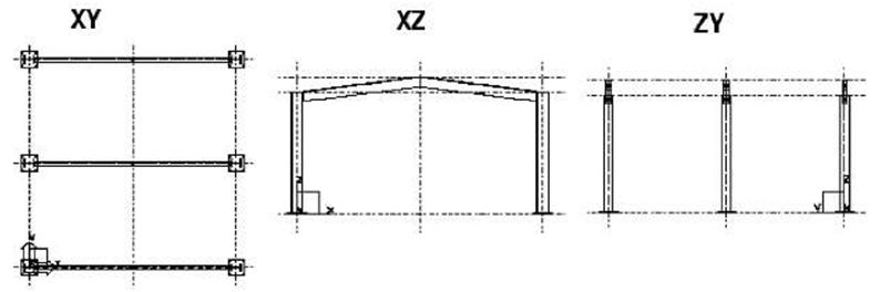
| Basic view plane | Each view has a view plane on which the grids are visible and points are represented as yellow crosses. Basic views are those parallel to the global basic planes, i.e. xy, xz, and zy. In basic views two axes always define the view plane and they appear in the plane name. The third axis is perpendicular to the view plane. It does not appear in the plane name. In the basic plane view, the model is shown from the direction of that third axis. The view plane options for basic views are: |
||||
 |
|||||
| View plane coordinate Other views |
For basic views, you also define at which distance from the global origin the view plane is in direction of the third axis. The view plane coordinate equals this distance. For view types other than basic views, you define the view plane and coordinate by picking points, e.g. With three points, or they are defined automatically according to the chosen creation method/command, e.g. To work plane. You can change the view plane by moving it like any other object. Click anywhere on the plain background, right-click and select Move Special > Linear… from the pop-up menu.. |
||||
| Moving the view plane | |||||
| ■s | Moving a view plane may result in a situation such that view depth and work area do not intersect and thus nothing can be seen in the window. | ||||
| View properties | |||||
| Naming views Tekla Structures numbers views in order of creation, so you do not have to give each view a specific name. You should give a view a unique name if you need to open it in later sessions. When you exit the model, Tekla Structures only saves named views. Tekla Structures does not save unnamed views when you close them. |
|||||
| J? | In multi-user mode, it is very important to give views unique names. If several users have different views with the same name, the view settings of one user may randomly override the settings of another user. | ||||
| Getting Started | |||||
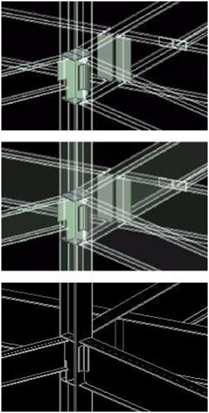
| View type The view type defines the appearance of the view. It also affects what methods you can use to rotate the model. The view type options are: • Wire frame Objects are transparent and their outlines are displayed. As the wire frame views use line graphics technique, redrawing views is quick. • Rendered Objects look more realistic because they are non-transparent and their surfaces are displayed as shown in the illustrations below. However, you can also choose the Wireframe or Shaded Wireframe option in the rendered views. Rotating the model in the rendered views is very convenient with the mouse. In rendered views, you can define how Tekla Structures displays parts and component objects separately. The following options are available: |
|||
| • Wireframe Part outlines are displayed, surfaces are not, i.e. parts are transparent. (In this example, component objects are displayed as Rendered.) • Shaded Wireframe Part outlines are displayed. Parts are transparent, and their surfaces are shaded. (In this example, component objects are displayed as Rendered.) |
 |
||
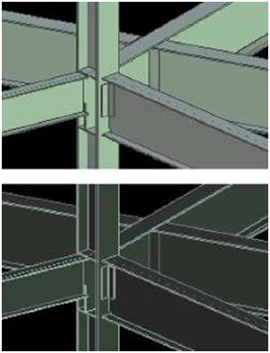
| • Hidden Lines Parts are not transparent, i.e. underlying parts are not visible. Part surfaces are not displayed. |
|||
| • Rendered Part surfaces are displayed, i.e. parts are not transparent. |
 |
||||
| • Rendered (Dark Colors) Parts are not transparent. Part outlines are displayed with brighter color, and part surfaces with darker color than in the Rendered option. |
|||||
| •7 | In rendered views, use the shortcuts Ctrl+1…5 and Shift+1…5 to set the desired representation for parts in the model and components. | ||||
| View angle | Projection If you choose the rendered view type, the projection can be: • Orthogonal All objects are of equal size (no perspective). When you zoom, text and point size remains the same. In addition, the zoom remains on part surfaces. • Perspective Distant objects appear smaller than close ones, as do text and points. You can zoom, rotate the model, or fly through it. Views can be: • Plane • 3D |
||||
 |
Use the shortcut Ctrl+P or click View > Switch to 3D / Plane to switch between 3D and plane view. | ||||
| Rotation | Rotation is view-specific. You can rotate the model in 3D views using the mouse and keyboard, or by defining the rotation angle in the View properties dialog box. You can specify rotation angles around the z axis and around the x axis. | ||||
| View depth | Every view has depth, which is the thickness of the displayed slice of model. You can define the depth separately upwards and downwards from the view plane. The objects within the displayed depth and the work area are visible in the model. However, objects created after the view are visible also outside the view depth | ||||
| Defining grid view properties | |||||
| Number of views |
Grid views are views along the grid lines. Before creating grid views, you can define how many views Tekla Structures will create, how it will name the views, and which view properties it will use. There are four options for the number of views: • None Tekla Structures does not create any views. • One (First) Tekla Structures only creates the view closest to the grid origin. • One (Last) Tekla Structures only creates the view furthest from the grid origin. • All Tekla Structures creates all views in grid planes in the relevant direction. View names consist of a prefix and a grid label, e.g. PLAN +3000. If the View name prefix field is left empty, no prefix is used. Tekla Structures adds a dash and a running number to the view name if view names are otherwise identical. Each view plane has its own view properties. You can load the properties from the current view properties with the option <applied values> or from saved view properties. The Show… button displays the view properties. |
||||
| View name prefix | |||||
| View properties | |||||
| Creating and modifying views | |||||
| Creating |
When you create a new model, you can select the Create default view and grid checkbox to have Tekla Structures automatically create a grid and a view according to the saved standard properties. To create views, use the commands on the View menu. The following table lists the commands for creating views and gives a short description of each one: |
||||
| Command | Icon Description | ||||
| Create View of Model > 3D View… | Displays the Create 3D View dialog box and creates a 3D view. | ||||
| Create View of Model > Using Two Points Create View of Model > Using Three Points |
Creates a view using two picked points. Creates a view using three picked points. |
||||
| Create View of Model > On Work Plane |  |
Creates a view of the current work plane. | |||
|
|||||||||||||||||||||||||||||||||||||||||||||||||||||||||||||||||||||||||||||||||
| Modifying | To modify a view, double-click anywhere on the plain background. The View Properties dialog box appears and you can modify the properties. | ||||||||||||||||||||||||||||||||||||||||||||||||||||||||||||||||||||||||||||||||
| Opening, closing, and deleting named views | |||||||||||||||||||||||||||||||||||||||||||||||||||||||||||||||||||||||||||||||||
| To view and open the existing named views, do one of the following: • Click 1-= . • Click View > View List… to display the Views dialog box. Tekla Structures lists all invisible named views on the left, and all visible views on the right. To display or hide views, select the view(s) and use the arrows between the lists. You can also double-click a view in the Views dialog box to open or close it. To select multiple views on lists, use the Shift and Ctrl keys when you select views. To deselect views, hold down the Ctrl key. To delete a named view, select the view and click Delete. |
|||||||||||||||||||||||||||||||||||||||||||||||||||||||||||||||||||||||||||||||||
| Refreshing the screen display | |||||||||||||||||||||||||||||||||||||||||||||||||||||||||||||||||||||||||||||||||
| Active window To update and display the contents of an active window, do one of the following: • Press Ctrl+U. • Right-click, then select Update Window. • Click View > Zoom > Active Window > Update. All windows To update the contents of all windows, click View > Update All. You can also use View > Redraw All to recalculate and redraw the contents of all the windows. Click Window > Close All to close all the windows on the screen at the same time. |
|||||||||||||||||||||||||||||||||||||||||||||||||||||||||||||||||||||||||||||||||
| Getting Started | |||||||||||||||||||||||||||||||||||||||||||||||||||||||||||||||||||||||||||||||||
| 2.4 Points | |||||||||||||||||||||||||||||||||
| Introduction | To place an object in a model you may need to pick points. To place an object where no lines or objects intersect, you have the following options to place objects: • Use snapping commands. • Use construction planes, lines and circles • Create points. There are many ways to create points in Tekla Structures. Which method is the most convenient at each time, depends on what you have already created in the model and which locations you can easily pick. When you create points, Tekla Structures always places them according to the work plane coordinate system. Points located in the view plane are yellow and points outside the view plane are red. |
||||||||||||||||||||||||||||||||
| Point properties | |||||||||||||||||||||||||||||||||
| To view the properties of a point, double-click the point or click Tools > Inquire > Object and select the point. Phase and ID Just like any other object, each point has an ID number which is used in log files. Points and parts have phase numbers. You can filter objects by their phase and ID numbers. Coordinates The point information you are most probably interested in is the local (work plane) and global x, y, and z coordinates of a point. Checking them convinces you of the correct location of the point or some other object related to it. |
|||||||||||||||||||||||||||||||||
| Creating points | |||||||||||||||||||||||||||||||||
|
To create points, use the icons on the Points toolbar, or select a command from Modeling > Add Points. The following table lists the commands for creating points and gives a short description of each one: |
|||||||||||||||||||||||||||||||||
|
|||||||||||||||||||||||||||||||||
| Command | Icon | Description | ||
| On Plane… | Displays the Point Array dialog box and creates a point array relative to the current work plane. | |||
| Projected Points on Line |  |
Projects a picked point onto a picked line. | ||
| Using Center and Arc Points | V. | Creates points along an arc. | ||
| Using Three Arc Points | Creates points as an extension of an arc defined by three picked points. | |||
| Tangent to Circle | Creates a point where a circle and a line meet tangentially. | |||
| At Intersection > Of Two Lines | Creates a point at the intersection of two lines. | |||
| At Intersection > Of Plane and Line | •£. | Creates a point where a line intersects with a plane. | ||
| At Intersection > Of Part and Line | Creates points where a line intersects with a part surface. | |||
| At Intersection > Of Circle and Line | \d | Creates points where a circle and a line intersect. | ||
| At Intersection > Of Two Part Axes | 4 |
Creates a point where the axes of two parts intersect, and projects the point onto the view plane. |
||
| At Any Position | Creates a point to any position you pick. | |||
| Bolt Points | ■B= | Creates points at the bolt center points of the picked bolt groups. | ||
| Grid Points | !# | Creates points at the intersections of grid lines on the view plane. | ||