
|
||||||||||||||||||||||||||||||
| 2. Enter the name of the setting in the text box next to the Save as button and click Save as. The object representation setting is saved in the model’s attributes folder. 3. Click the Add row button to add a new row. 4. In the Object group column, select a predefined object group from the list box. OR Select Create new group… to create a new object group. 5. Select coloring for the objects in the object group, in the Color column. 6. Select the Transparency setting. 7. Use the Add row button to add more rows. 8. Click Save to save the object representation settings. 9. Click Modify to preview the settings in the views. 10. Click Apply and OK. |
||||||||||||||||||||||||||||||
| If you click Modify, Apply, or OK, Tekla Structures adds a row All to lowest down, if the object representation settings did not contain the group All. The default values for row All are Color by class and Visible. To define the color of some model objects, click View > Representation > Object representation…. The Color settings are:
|
||||||||||||||||||||||||||||||
|
||||||||||||||||||||||||||||||
| TEKLA STRUCTURES 14.0 145 Settings and Tools | ||||||||||||||||||||||||||||||

|
|||||||||||||||||||||||||||||||||||||
| Transparency The Transparency settings are: |
|||||||||||||||||||||||||||||||||||||
|
|||||||||||||||||||||||||||||||||||||
| Object representation files Tekla Structures saves object representation settings with filename extension *.rep in the current model’s attributes folder. • You can copy the object representation setting file to another model’s attributes folder. • To make the object representation setting available to all models, copy the file to the system folder. Tekla Structures searches for the object representation files in the standard search order. For more information, see Folder search order in the online help. Object groups are sets of rules with which you can group objects by selected properties and conditions. Use the object groups: • In view filter, to define which objects are displayed in the selected view. • In select filter, to define which objects can be selected. • In the Object Representation dialog box, to control the transparency and coloring of objects in all views. |
|||||||||||||||||||||||||||||||||||||
| 146 TEKLA STRUCTURES 14.0 Settings and Tools | |||||||||||||||||||||||||||||||||||||
| Topics | • In the Project Status Visualization tool. Creating object groups To create a new object group: 1. Click View > Representation > Object Representation… to open the dialog box. 2. Select Create new group… in the list box in the Object group column, and the Object group – representation dialog box opens. 3. Enter the name of the object group and click Save as. • The object group you create is saved in the model’s attributes folder. 4. Click Add row to define a rule. • Rule is based on selected Category, Property, Condition, and Value. . 5. Use the Add row button to add rows for more rules. Use the Delete row and Delete all buttons when needed. 6. When the set of rules is ready, click Save. 7. Click Close. 8. The new object group is shown in the Object representation dialog box. Tekla Structures saves object group representation files with filename extension *.PObjGrp. Tekla Structures has three different object group types: view filter, selection filter, and object representation. All these use different object group files, so you cannot, for example, use selection filter object groups in the view filter. Object group filename extensions depend on the purpose the group was created for: |
|||||||||||||||||||||||||||
| Filenames | ||||||||||||||||||||||||||||
| Filename extension | ||||||||||||||||||||||||||||
|
||||||||||||||||||||||||||||
| File location Object groups are saved in the current model’s attributes folder. • To make an object group available in another model, copy its file to the attributes folder of the destination model. • To make an object group available in all models, copy its file to the system folder. You must restart Tekla Structures to apply the changes. Tekla Structures searches for the object group files in the default order. For more information, see Folder search order in the online help. |
||||||||||||||||||||||||||||
| TEKLA STRUCTURES 14.0 147 Settings and Tools | ||||||||||||||||||||||||||||
| ■s | A consistent naming policy for created object groups is important, as handling the object group files is done manually in the model, project, firm, and system folders. | |||||||||||||||||||||||||||||||||||||||||||
| Deleting an object group See also |
To delete an object group, delete the object group representation file located in the attributes folder. In the object group dialog box, you can add, delete, and modify the rules on which the object group is based. The object group rules include the following options: |
|||||||||||||||||||||||||||||||||||||||||||
|
||||||||||||||||||||||||||||||||||||||||||||
| 148 TEKLA STRUCTURES 14.0 Settings and Tools | ||||||||||||||||||||||||||||||||||||||||||||
|
|||||||||||||||||||||||||||||||||||
| To add a rule: | |||||||||||||||||||||||||||||||||||
| 1. In the object group dialog box, click Add row. 2. Select Category from the list box. 3. Select Property from the list box. 4. Select Condition. 5. Enter the value in the Value column, or select the value from the model. 6. Add more rows and use And/Or column and parentheses to create more complex rules. Using dates in the object group rules To use date rules in the object groups: 1. Open the Object group – representation dialog box and add a row to the group. 2. Select, for example, Object in the Category column. 3. Select, for example, user-defined attribute Actual erection date in the Property column. 4. Select Condition. With date properties, you can use the following conditions: • Equals • Does not equal • Later than • Later than or equal • Earlier than • Earlier than or equal 5. In the Value column, click Select date… to open the Select date dialog box. The dialog box includes the following options: |
|||||||||||||||||||||||||||||||||||
| TEKLA STRUCTURES 14.0 149 Settings and Tools | |||||||||||||||||||||||||||||||||||
|
|||||||||||||||||||||||||||||
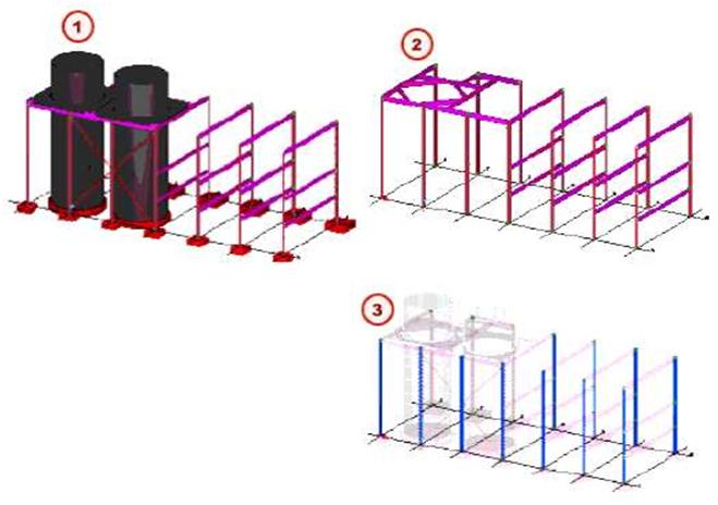
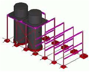
| 6. Select the date option and click OK. In this example, we create a visualization for parts with different value for the user-defined attribute Planned erection date. The parts will have the following colors: • Blue if the planned date is earlier than the review date. • Green if the planned date is the same as the review date. • Yellow if the planned date is one day after the review date. • Red if the planned date is two days after the review date. This is how the model looks with standard object representation settings: |
|||||||||||||||||||||||||||||
 |
|||||||||||||||||||||||||||||
| To create object representation settings and object groups that define which objects should get the coloring defined above: 1. Click Setup > Object representation… to open Object representation dialog box. 2. Name the empty object representation, for example, as plan_test. By default, the object representation dialog box includes an object group All. Do not delete this group, but keep it last in the list. 3. Click Add row to add a new row. 4. Select the newly added row, and click Create new group… in the Object group list box. The Object group – representation dialog box opens. |
|||||||||||||||||||||||||||||
| 150 TEKLA STRUCTURES 14.0 Settings and Tools | |||||||||||||||||||||||||||||
| 5. Enter a name for the group, for example, plan_before_review_date. 6. Click Save as. 7. Modify the rule. This rule includes objects that have user-defined attribute Planned erection date set earlier than the review date. • Select Object in the Category column. • Select Planned erection date in the Property column. • Select Earlier than in the Condition column. • Click Select date… in the Value list box and select Review date in the Select date dialog box and click OK. 8. Click Save and Close. 9. In the Object representation dialog box, select blue in the Color list box of the plan_before_review_date row and check that the object group is set to Visible. Repeat steps 3 to 9 and create three more object groups with different rules: • Object group plan_review_date, with the following rule: Object Planned erection date Equals Review date. • Object group plan_one_day_after, with the following rule: Object Planned erection date Equals 1 day(s) after the review date. • Object group plan_two_days_after, with the following rule: Object Planned erection date Equals 2 day(s) after the review date. |
||
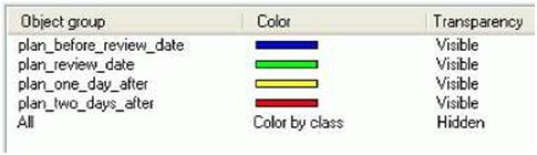
| 10. When all object groups are created, set the color and visibility of the object groups, in the Object representation dialog box, to be the following: | ||
 |
||
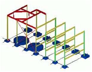
| 11. Select Hidden in the Transparency column for the All object group and check that it is last in the list. 12. Click Save and Modify. The model is now shown with the defined colors: |
||
 |