Tekla Structures – Examining the model

Examining the model
Zoom commands

The zoom tools allow you to focus in on a particular area, or pull out for a wider view. You can use a mouse, or keystrokes, or a combination of both. You use the majority of these tools within an existing view. However, a zoom window must be open to use the Magnifier and Pan tools.

The Zoom commands are:

TEKLA STRUCTURES 14.0 125 Settings and Tools


Zoom command Icon Description
Zoom in Works within the existing view.
•”
Zoom out p Works within the existing view.
Zoom original Vp\ Restores the original level of zoom. Works within the existing view.
Zoom previous Restores the previous zoom. Use this to switch between the last two zooms. Works within the existing view.
Create zoom window Creates a new zoom window from an existing view. You can only create zoom windows from wire frame views. The zoom window contains two additional commands, Magnifier and Pan.
Active window The commands below Active window automatically zoom the active window. So you do not need an extra click to complete the command.
Magnifier
Pan
Zooming with mouse
Use the Zoom in tool to focus in on a specific area of the model. The Zoom out tool pulls out for a wider view. Both work within an existing view window. How you use the zoom tools depends on the pointing device you are using: a 3-button mouse, or a wheel mouse.
3-button mouse

To use zoom with a 3-button mouse:

1.    Open the model.

2.     Click the zoom in or zoom out icon on the Zoom toolbar.

3.    Click the area of the model that you want to examine.

4.    Continue to click to zoom further in or out.

Wheel mouse

Tekla Structures has two zoom modes you can use with a wheel mouse:

•      In mouse-wheel mode, scroll the wheel to zoom in and out.

•      In scroll mode, you can also hold down the wheel when scrolling. To use zoom with a wheel mouse:

1.    Open the model.

2.     Click the zoom in or zoom out icon on the Zoom toolbar.

126 TEKLA STRUCTURES 14.0 Settings and Tools
3.    Click the area of the model that you want to examine.
4.    Scroll forward to zoom in, scroll backward to zoom out.

Using keystrokes

To zoom using keystrokes:

1.    Open the model.

2.     With the mouse cursor over the model, press Page Up to zoom in, Page Down to zoom out.

Zoom settings
Centered zooms To keep the center point of the view in the middle of the view window, regardless of the position of the pointer, check Centered zooms on the Setup menu.
If Centered zooms is not checked, the pointer does not move.

Zoom ratio                  The following variables control how much you zoom in or out with each click.

3-button mouse Use the variable XS_ZOOM_STEP_RATIO to control the zoom ratio when using a 3-button

mouse. The default value is 0.25. Increase this value to zoom in or out more with each click.

Wheel mouse            To set the zoom ratio when scrolling (not holding down) the

wheel, use the variable XS_ZOOM_STEP_RATIO_IN_MOUSEWHEEL_MODE.

To set the zoom ratio when scrolling and holding down the wheel, use the variable XS_ZOOM_STEP_RATION_IN_SCROLL_MODE.

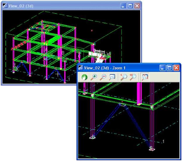
Creating a zoom window
Opening a zoom window gives you access to additional tools, the Magnifier
and Pan These appear on the toolbar within the zoom window.
You can only create zoom windows from wire frame views.
To create a zoom window:
1.     In the View Properties dialog box, click Wire frame in the View type list box.

2.    Click Modify.

3.    Click View > Zoom > Create Zoom Window.

4.    Click a starting corner for the zoom window, then drag the pointer to size the window. Release the mouse button to create the window.

5.    Move the zoom window to a convenient location on the screen.

6.    Resize the zoom window by dragging the window boundaries.

Magnifier
The Magnifier is useful when you need to keep a general view of the model open, and examine particular areas in detail, at the same time.
To use the Magnifier, you must have both a general view window containing the model and a zoom window open
TEKLA STRUCTURES 14.0 127 Settings and Tools
Click the Magnifier icon J in the zoom window. As you move the pointer in the general view, the zoom window displays the area around the pointer in detail, as shown in the example below. Change the level of magnification by zooming in and out in the zoom window.
Moving the model in the view window
In Tekla Structures you can move, pan, rotate or fly through a model, in the view window.
Center by cursor Move

The Move commands move the viewpoint (or camera) rather than the model itself. Use the up, down, left and right arrows on the keyboard to move the viewpoint. You can also click View > Move to use the move commands.

To center the model on a particular point, click View > Move > Center by Cursor, then click anywhere in the view to center the view on that point.

128 TEKLA STRUCTURES 14.0 Settings and Tools
Pan
The Pan command moves the model itself. Activate dynamic panning using the P key on your keyboard, or click View > Move > Pan. The pointer will change to a hand. Click and drag the mouse to move the model anywhere within the view window.

You can also pan while using the Fly command. To do this, activate the Fly command, and use the middle mouse button to pan when needed.

Rotating the model

You can use keystrokes, menu commands, the mouse, or a combination of these techniques to rotate the model.

Rendered view In rendered views, you can rotate the model around the existing center of rotation. Hold down
the Ctrl key and click and drag with the middle mouse button.
To relocate the center of rotation:

1.    Press the V key.

2.    Click to pick the new center of rotation.

Or:

1.    Use the keystrokes Ctrl+R.

2.    Click to pick the new center of rotation.

3.    Click and drag with the left mouse button to rotate the model.

4.     Use the Esc key or Interrupt to end rotation.

You also have the following keyboard options to rotate the model around the existing center of rotation:

Keyboard technique
Wire frame                  In wire frame view, you can only use the keyboard technique to rotate a model. The center of
rotation is fixed in the center of the work area.

Automatic                   Click View > Rotate. You have the following options:

rotation

Click Esc to stop rotation.
TEKLA STRUCTURES 14.0 129 Settings and Tools
T

Snap affect model rotation. For example, with Free active, you can click anywhere to define the center of rotation. If Free is inactive, you need to pick an intersection point, or the end of a part.

Disable view             To disable or enable view rotation, click Window > Rotate > Disable view rotation, or use F8.
rotation

Flying through the model

In Tekla Structures, you can travel through a model, changing direction and varying speed as you go.

Start flying

To fly through a model, you must have a rendered view open, with Projection set to Perspective. See View properties for more infromation on how to change view properties. Use the keyboard shortcut Shift+F to start flying though the model, or click View > Fly.

Pick the view to fly in.Tekla Structures displays an arrow symbol to indicate the flying direction.

See also                      View properties

Stop flying

Use Interrupt to stop flying

Adjust speed

To adjust your flying speed, move the mouse to the desired flying direction. The flying speed grows exponentially when you are approaching the model from a distance.

Change direction

To fly forward, move the mouse forward. To change the flying direction, move the mouse to the desired direction.

Changing the level of flying

1. To change the level you are flying on and to go straight up or down, hold down the Ctrl key and move the mouse forward to go up, and backwards to go down. Release the Ctrl key to continue flying on a level.

Changing the camera angle

1. To change the camera angle, scroll with the mouse wheel. To fly in the in the direction of the camera angle, hold down the Shift key and scroll forwards to go down or backwards to go up.

Creating clip planes

In Tekla Structures, you can create up to six clip planes in any rendered model view. Using clip planes enables you to focus in on the required detail in the model.

To create a clip plane:

1. Select a rendered model view.

130 TEKLA STRUCTURES 14.0 Settings and Tools
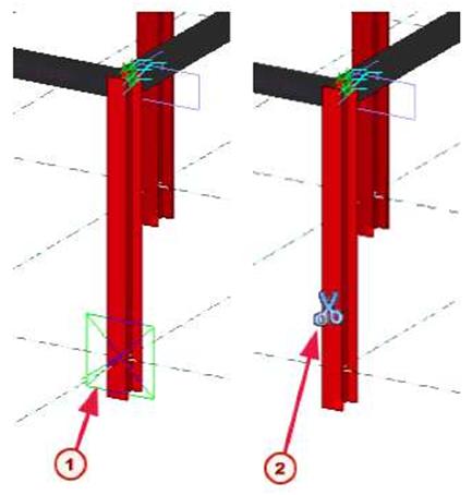
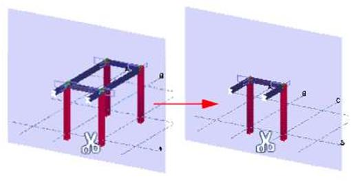
2.     Start the Create clip plane command:
•        Right-click and select Create clip plane from the pop-up menu, or

•       Click View > Create clip plane.

3.    To select the position of the clip plane, click a plane.

4.     To finish, right-click and select Interrupt.

5.    The clip plane symbol appears in the model:

(T) Selected plane t2J Clip plane symbol
To move the clip plane, click the symbol, and drag it to a new location.
To delete a clip plane, click the clip plane symbol and press Delete.

Leave a Comment

This site uses Akismet to reduce spam. Learn how your comment data is processed.