
| T? | Measurements appear in the rendered view window, until you update or redraw the window. | |||||
| Click Tools > Measure to access the following options. Remember to follow the prompts on the status bar. The steps for each option are listed below the table. | ||||||
| Option | Icon | Action | ||||
| Distance | ** |
Measures a user-defined distance between any two points. You can use this option to measure inclined or aligned distances in the current view plane. |
||||
| Horizontal Distance | n | Measures the x distance between two points on the view plane. | ||||
| Vertical Distance | Measures the y distance between two points on the view plane. | |||||
| Angle | . i | Measures angles. | ||||
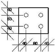
| Bolt Spacing | » | Measures bolt spacing and edge distances in the selected part. | ||||
| Horizontal, vertical and user-defined | To measure horizontal, vertical and user-defined distances: 1. Click Tools > Measure and select one of the options. 2. Pick the starting point. 3. Pick the end point. 4. Click to indicate on which side of the dimension line you want the number to appear. To measure angles: 1. Click Tools > Measure > Angle. 2. Pick the center point. 3. Pick the starting point. 4. Pick the end point. (Counterclockwise from the starting point.) Use this option to measure the distances between bolts in a bolt group. Tekla Structures also gives you the edge distances between the bolts and a selected part. To measure bolt spacing: 1. Click Tools > Measure > Bolt Spacing. 2. Pick a bolt group. 3. Pick a part. |
|||||
| Angles | ||||||
| Bolts | ||||||
| TEKLA STRUCTURES 14.0 133 Settings and Tools | ||||||
 |
|||||
| See also | XS_VIEW_FREE_MEASURE_PLANE | ||||
| Clash check | |||||
| When you have completed your model, run the Clash check to find parts, bolts, or reference model objects that collide. | |||||
 |
Clashes of objects that are only touching one another are not included in the clash check log. | ||||
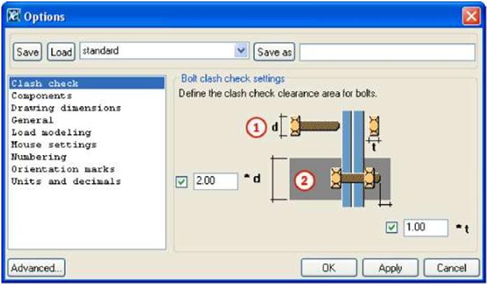
| Steps | 1. Select the objects you want to check. 2. Click Tools > Clash check. 3. The clash check progress is displayed in the status bar. You can continue working during the clash check. If there are no colliding parts, Tekla Structures displays the message No collisions detected on the status bar. If parts, bolts, or reference model objects collide, Tekla Structures highlights them in yellow and displays the clash check log in the List dialog box. If you start clash checking while another clash check is still running, you can choose whether to continue checking, restart the operation and check the currently selected parts, or stop checking. 4. To quickly locate and view colliding parts in the model, select the line containing the ID numbers of colliding parts from the list. Tekla Structures highlights the parts in the model. Hold down the F key while you do this to have Tekla Structures fit the work area. To define bolt clearance for clash checking, click Tools > Options > Options… > Clash check. Enter the values in the Bolt clash check settings dialog box. |
||||
| Set bolt clearance | |||||
 |
||||
| MJ d is the larger value of the bolt head or nut diameters (2) Clash check clearence | ||||
| Reference models |
The clash checking clearance area is grey. Select the checkbox in front of the field if you want to use the clearance value. If you clear the checkboxes, the clearance will be zero.The clearance in front of the bolt head is equal to the bolt length. If you do not enter values for clearances, Tekla Structures uses the default value of 1.00. You need to save the clearance values to use them in future sessions. Click Tools > Defaults > Save Defaults. If Tekla Structures cannot find the bolt head or nut diameter in the bolt catalog, it uses the shank diameter. The following reference model file types are supported in clash checking: • IFC • DWG • DGN |
|||
| 5 | If you are working on a large model, running the clash check may sometimes be slow. In that case you can use the old clash checking functionality, which does not recognize clashes with reference models. For more information, see XS_USE_NEW_CLASH_CHECK and XS_CLASH_CHECK_BETWEEN_REFERENCES. |
|||
| Compare | ||||
| Use this tool to compare two assemblies or parts. | ||||
| TEKLA STRUCTURES 14.0 135 Settings and Tools | ||||
| To compare parts, select two parts in the model. Click Tools > Compare > Parts. To compare assemblies, click on a part in each assembly. Click Tools > Compare > Assemblies. Tekla Structures displays the results on the status bar. |
|||
 |
|||
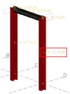
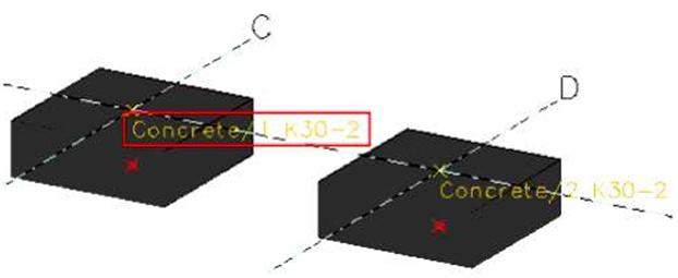
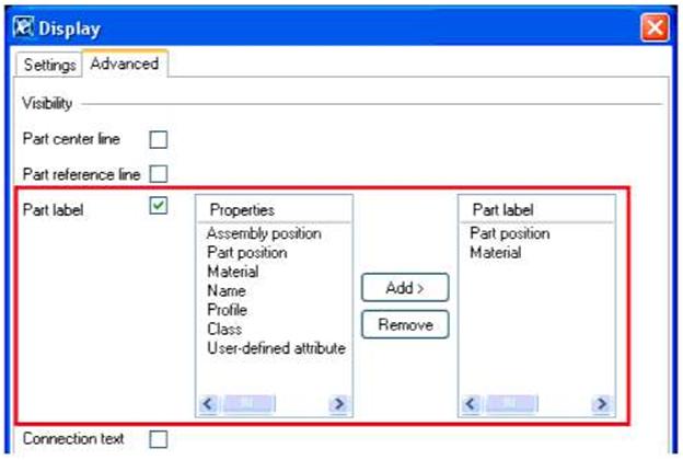
| Part labels | |||
| Use the Part label option to display selected part properties, user-defined attributes, and template attributes in a model view: | |||
 |
|||
 |
|||
| To use the Part label option in a model view: 1. Double-click the view to open the View properties dialog box. 2. Click Display…. The Display dialog box appears. 3. Click the Advanced tab and select the Part label checkbox. |
|||
| 136 TEKLA STRUCTURES 14.0 Settings and Tools | |||
 |
|||
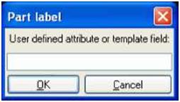
| To add a property to the part label: 1. Select a property on the Properties list. 2. Click Add to add it to the Part label list. To add a user-defined attribute or template attribute to the part label: 1. Select User-defined attribute on the Properties list. 2. Click Add. The Part label dialog box appears: |
|||
 |
|||
| 3. Enter the attribute name and click OK. For more information on the Display dialog box, see Display in the online help. |
|||
| Finding distant objects | |||
| When the work area is huge, the model may contain some distant objects that are not easy to find. Use the Find Distant Objects command to find these objects. | |||
 |
You cannot use this command to find parts (such as beams, columns or plates). | ||
| To find distant objects: | |||
| TEKLA STRUCTURES 14.0 137 Settings and Tools | |||
| 1. Click Tools > Diagnose & Repair Model > Find Distant Objects. Tekla Structures displays a list of object IDs. 2. Select an object in the list. 3. Right-click and select a command from the pop-up menu. You can, for example, inquire or delete the object. See also XS_DISTANT_OBJECT_FINDER_TOLERANCE |
|||