
| The Sketching toolbar is embedded in the Cross section sketch editor. It contains thetools you need to define and save cross sections: | ||||
 |
||||
 |
Tekla Structures will not save a cross section that does not have dimensions. | |||||
| Using constraints to lock cross section shape | ||||||
| After you have sketched the outline of a cross section, use the constraint tools to refine your sketch and lock the shape, for example, to straighten lines, create 90° angles, force lines to meet, and close the shape. The Sketching toolbar includes the following tools to create constraints: |
||||||
| Command | Icon | Description | ||||
| Sketch radial dimension |  |
Creates a radial constraint for an arc or circle. | ||||
| Sketch angle dimension | te | Creates an angle constraint for an arc or circle. | ||||
| Parallel constraint |  |
Force a line to be parallel to another line. | ||||
| Perpendicular constraint | Fi | Force a line to be perpendicular to another line. | ||||
| Coincident constraint |  |
Force two lines to meet (extends or shortens one or both lines.) Useful when you need to close a shape. Tekla Structures automatically creates coincident constraints: • Where 2 lines meet • Between line segments when you draw them with the Sketchpolyline tool. • Between the start of the first line segment and the end of the last line segment in a shape, if they are within a certain distance of each other. |
||||
| Fixed constraint |  |
Locks the position and angle of a line, so that other constraints do not affect it. | ||||
| TEKLA STRUCTURES 14.0 Advanced Modeling | 197 | |||||
|
|||||||||||||||||||||||||||||
| See also | See the online help for a step-by-step example on using these tools. Sketching cross sections (p. 196) You can choose to create chamfers in your cross section. Then you need to add dimensions, and save your sketch. See: • Defining chamfers (p. 199) • Adding dimensions to cross sections (p. 199) • Naming, saving, and closing cross sections (p. 205) |
||||||||||||||||||||||||||||
 |
Tekla Structures will not save a cross section that does not have dimensions. | ||||||||||||||||||||||||||||
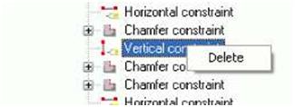
| Deleting constraints To delete a constraint: 1. Click the Sketch Browser icon 2. Select the constraint in the Sketch Browser dialog box. 3. Right-click and select Delete from the pop-up menu: |
|||||||||||||||||||||||||||||
 |
|||||||||||||||||||||||||||||
| 198 TEKLA STRUCTURES14.0 Advanced Modeling | |||||||||||||||||||||||||||||
| Defining chamfers | ||||
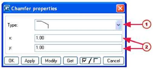
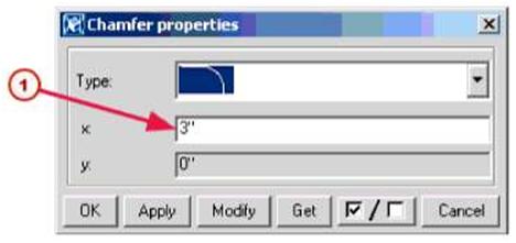
| When you use the Create polyline tool to sketch a profile, Tekla Structures automatically creates coincident constraints between the line segments and displays a chamfer symbol where line segments meet EEl. To change the shape or dimensions of a chamfer: 1. For each chamfer you want to change, double-click the chamfer symbol in the sketch. Tekla Structures opens the Chamfer properties dialog box. 2. Change the shape and dimensions of the chamfer. |
||||
 |
||||
| (T) Select chamfer shape fa)Enter chamfer dimensions | ||||
| 3. Click Modify to modify the chamfer. 4. Click OK to close the Chamfer properties dialog box. 5. Click the Save sketch icon to save the changes. |
||||
| Adding dimensions to cross sections | ||||
| After you have sketched a parametric cross section, use the dimension constraint tools on the Sketching tool bar to create dimensions for it. You can use these dimensions to define the size of the profile cross section when you use it in a model. Tekla Structures also adds the dimensions you create to the list of variables that you can use in calculations. See Using variables to define cross section properties (p. 201). |
||||
 |
Tekla Structures will not save a parametric cross section that does not have dimension constraints. | |||
| The Sketching toolbar includes the following tools to create dimensions. | ||||
| TEKLA STRUCTURES 14.0 Advanced Modeling | 199 | |||
|
||||||||||||||||||||||||||||||||||||||||||||||
| Using planes to position parts and connections | ||||||||||||||||||||||||||||||||||||||||||||||
| Part positioning planes | By default, Tekla Structures determines the position of parts using the outline of the part or connection, together with the options you select in the Positions section of thePosition tab in the part properties dialog box. For example, the Middle option positions apart based on the geometric center of the part profile. See also Part location (p. 82). You can have Tekla Structures use part positioning planes instead of the part profileoutline to calculate the On plane and At Depth part position options. For example, you can create part positioning planes that define the Middle optionof an asymmetrical profile: |
|||||||||||||||||||||||||||||||||||||||||||||
 |
||||||||||||||||||||||||||||||||||||||||||||||
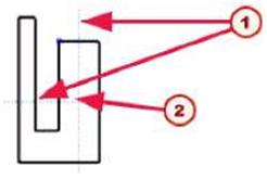
| © © | Part positioning planes Middle option based on the intersection of part positioning planes, not part outline |
|||||||||||||||||||||||||||||||||||||||||||||
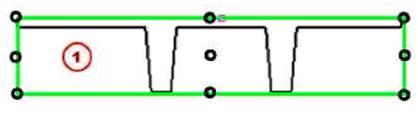
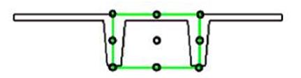
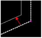
| The part positioning planes appear as blue lines in the Cross section sketch editor view. Connection Tekla Structures uses connection positioning planes to define the position of components positioning relative to parts. Connection positioning planes appear as green lines in the Cross section planes sketch editor view. The following image shows the default connection positioning planes and locations where you can place details when the part is a double tee slab created as sketched cross section. |
||||||||||||||||||||||||||||||||||||||||||||||
 |
||||||||||||||||||||||||||||||||||||||||||||||
| 200 TEKLA STRUCTURES14.0 Advanced Modeling | ||||||||||||||||||||||||||||||||||||||||||||||
| MJ The green line illustrates the default connection positioning planes | |||||||||||||||||||||||||||||
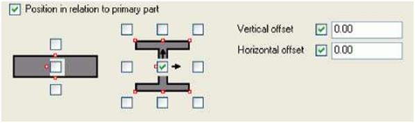
| When creating a detail to the slab, select the detail location using the following checkboxes on the General tab in the component dialog box. | |||||||||||||||||||||||||||||
 |
|||||||||||||||||||||||||||||
| If you want to place details as in the image below, you need to move connection positioning planes. | |||||||||||||||||||||||||||||
 |
|||||||||||||||||||||||||||||
| Tools | The Sketching toolbar includes the following tools to define positioning planes: | ||||||||||||||||||||||||||||
|
|||||||||||||||||||||||||||||
| Using variables to define cross section properties | |||||||||||||||||||||||||||||
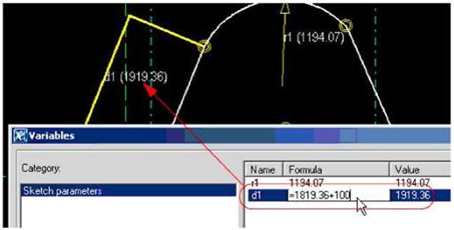
| You can define variables to define the properties of a sketched cross section. Variablescan define fixed properties, or they can include formulas, so that Tekla Structures calculates the property value each time you use the profile in a model. For example, you can create a variable that calculates a dimension: | |||||||||||||||||||||||||||||
| TEKLA STRUCTURES 14.0 Advanced Modeling | 201 | ||||||||||||||||||||||||||||
 |
|||||||||||||||||||||||||||
| The Sketching toolbar includes the following tools to create and use variables: | |||||||||||||||||||||||||||
|
|||||||||||||||||||||||||||
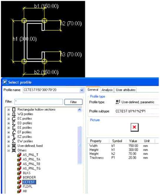
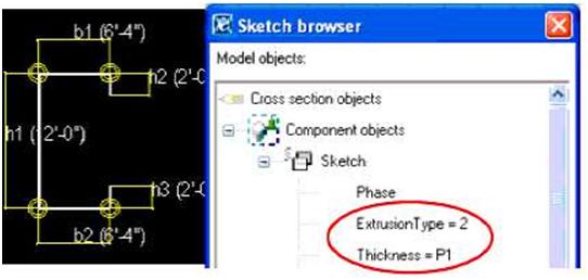
| Example: Symmetric C This example shows how to use the Variables dialog box and Sketch Browser. Wecreate a symmetric C-shaped cross section with b1 = b2 and h2 = h3. When you use the profile in the model, you can change the following dimensions: • Thickness (P1) • Total height (h1) • Height (h2) • Width (b1) |
|||||||||||||||||||||||||||
| 202 TEKLA STRUCTURES14.0 Advanced Modeling | |||||||||||||||||||||||||||
 |
|||
| First, create the cross section and distances: 1. Click Modeling > Profiles > Define Cross Section in Sketch Editor… to open the sketch editor. 2. Use the Sketch polyline command to create a C-shaped cross section. 3. Use the Sketch horizontal distance and Sketch vertical distance commands to create all distances. All the created distances are automatically displayed in the Variables dialogbox. • To change the distance value, click the Formula cell and enter a new value. • To make the profile symmetric, type =h2 in the Formula cell of distance h3 and=b1 of distance b2. |
|||
| TEKLA STRUCTURES 14.0 Advanced Modeling | 203 | ||
 |
||||
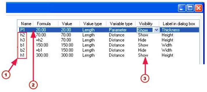
| © | Distances from the sketch | |||
| f2J Add this parameter to enter varying values for profile thickness | ||||
| /T\ If you want to give variables different values when using the profile, set | ||||
| Visibility to Show | ||||
| To add the P1 variable for profile thickness: 1. In the Variables dialog box, click the Add button. 2. Click the Formula cell and enter a thickness value. 3. In the Visiblity cell, select Show. 4. Type Thickness in the Label in dialog box cell. 5. In the Sketch Browser, right-click the Thickness object and select Add equationfrom the pop-up menu. Then type in =P1. |
||||
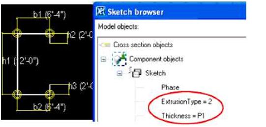 |
||||
| 6. Right-click the ExtrusionType object and select Add equation from the pop-up menu. Then type in =2. For more information about the ExtrusionType, see Extruding sketched polyline (p. 207). | ||||
| 204 TEKLA STRUCTURES14.0 Advanced Modeling | ||||
| Creating a picture of a cross section | |||||||||||||||||||||||||||||
| Using screenshot | Library profiles include pictures which illustrate the shape and dimensions of each profile. To add pictures of sketched parametric cross sections: 1. Using any image editor, e.g. Paint, create an image that shows the shape and dimensions of the profile. 2. Save the image in the folder..\TeklaStructures\*version*\nt\bitmaps, using the cross section name as the filename, with the file extension .bmp. For example, mysketch.bmp. To use a Tekla Structures screenshot as a picture: 1. Open the sketch in the cross section sketch editor view. If necessary, click in the sketch to ensure it is the active view. 2. Press F12 on your keyboard to take a screenshot of the sketch, without the borders. 3. In any file manager, e.g. Microsoft Explorer, rename the screenshot file to have the same name as the sketch, with the extension bmp. 4. Copy the renamed file to the folder..\TeklaStructures\*version*\nt\bitmaps. 5. Tekla Structures displays a picture of the sketch when you browse for profiles. |
||||||||||||||||||||||||||||
| Naming, saving, and closing cross sections | |||||||||||||||||||||||||||||
| Tekla Structures saves sketched cross sections in the profile catalog in the current model folder. | |||||||||||||||||||||||||||||
 |
Tekla Structures will not save a cross section that does not have dimensions. See Adding dimensions to cross sections (p. 199). | ||||||||||||||||||||||||||||
| The Sketching toolbar includes the following tools to name and save sketched cross sections: | |||||||||||||||||||||||||||||
|
|||||||||||||||||||||||||||||
| Testing your cross section | |||||||||||||||||||||||||||||
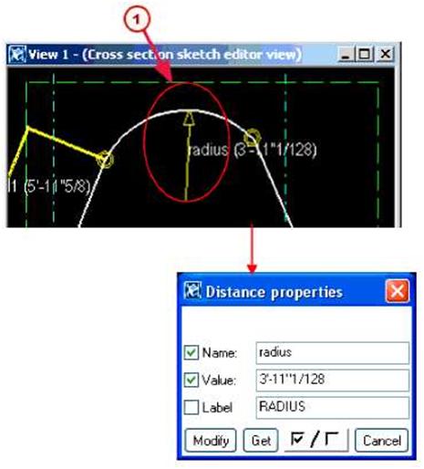
| To check that the constraints and dimensions in a sketched cross section work correctly, try this test: • Double-click a dimension line to open the Distance properties dialog box. • Change the Value field then click the Modify button. Tekla Structures updates thecross section in the sketch editor. • Check that the shape of the profile does not change and that the dimensions adjust correctly. Click the Cancel button to close the dialog box. |
|||||||||||||||||||||||||||||
| TEKLA STRUCTURES 14.0205 Advanced Modeling | |||||||||||||||||||||||||||||
| Modifying sketched cross sections | ||||
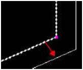
| To modify an existing sketched cross section: 1. Click Modeling > Profiles > Edit Cross Section in Sketch Editor…. TheComponent Catalog dialog box opens. 2. Double-click the name of the cross section to open it in the Cross Section Sketch Editor View. 3. The elements you can edit appear in yellow. For example, you can edit distances and chamfers. Double-click an element to edit its properties: |
||||
 |
||||
| f-M Double-click an element to edit its properties | ||||
 |
You cannot change dimensions that have been calculated using formulas in the Variables dialog box. Constraints may also prevent you from changing dimensions. See Using constraints to lock cross section shape (p. 197). |
|||
| Modifying chamfers To modify the shape or dimensions of a chamfer in a sketch: |
||||
| 1. Double-click the chamfer symbol HS9. 2. Modify the properties in the Chamfer properties dialog box: |
||||
| 206 TEKLA STRUCTURES14.0 Advanced Modeling | ||||
 |
|||
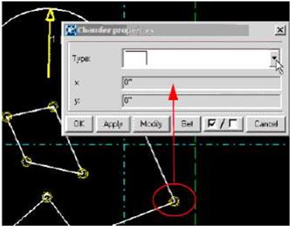
| Select a chamfer shape from the Type dropdown list. According to the shape of the chamfer, use the x and y fields to define its dimensions: |
|||
 |
|||
| © | Use the x field to define the radius of this convex chamfer | ||
| 3. Click the Modify button to change the chamfer. 4. Click the OK button to close the Chamfer properties dialog box. You can also copy and move the entire sketch or parts of it with the copy and move commands. For more information, see Copy (p. 138) and Move (p. 140). |
|||
| Extruding sketched polyline | |||
| To easily create a cold-rolled cross section (of a consistent thickness), sketch an open polyline, and define the extrusion type and thickness of the profile in the Sketch Browser: | |||
| TEKLA STRUCTURES 14.0207 Advanced Modeling | |||
 |
||||
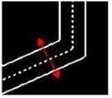
| The Extrusion type defines how the polyline is extruded. The options are: | ||||
| Sketch editor view | Sketch Browser dialog box | Description | ||
 |
Extrusion Type = 0 | Default. Polyline is extruded symmetrically from the center of the sketched line. |
||
 |
Extrusion Type = 1 | Polyline extruded to the outside of the sketched line. | ||
 |
Extrusion Type = 2 | Polyline extruded to the inside of the sketched line. | ||
| To define the thickness: 1. In the Variables dialog box, add a new length variable, for example P1, and enter thedefault thickness in the Formula cell. 2. In the Sketch Browser, set Thickness = P1 (the new variable). If you define thethickness value directly in the Sketch Browser, it means that thickness has a fixedvalue (Thickness = 10). 3. See also Example: Symmetric C (p. 202). |
||||
| 208 TEKLA STRUCTURES14.0 Advanced Modeling | ||||
| Using sketched cross sections in models | ||||
|
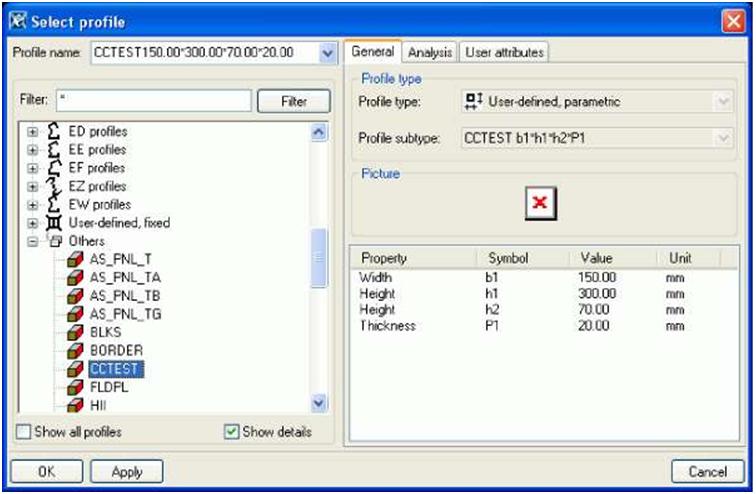
Once you have created a cross section and saved it in the profile catalog, you are ready to use it in the model. If you have applied constraints correctly, the shape of the profile will not change if you change its dimensions. See Testing your cross section (p. 205) for more information. To use the profile cross section in a model: 1. Double-click the part icon to open the part properties dialog box. For example, double-click the Create beam icon to open the Beam Properties dialog box. 2. To select a profile to use: • For steel parts, click the Select… button next to the Profile field. • For concrete parts, click the … button next to the Profile field. 3. The Select Profile dialog box opens. 4. Select the sketched parametric cross section. They appear under the Others profiletype at the end of the profile tree: |
||||
 |
||||
| See also | 5. To change the dimensions of the profile, click a dimension in the Value column inthe properties table in the lower part of the dialog box. Enter a new value, thenclick Apply. 6. Click OK to close the Select Profile dialog box. 7. In the part properties dialog box, click Modify to change the part profile in the model. 8. Click OK to close the part properties dialogbox. Importing and exporting sketches (p. 209) |
|||
| Importing and exporting sketches | ||||
| To use a sketched cross section in other models, you have to export the cross section sketch to a file (.uel), and then import the file into another model. | ||||
| TEKLA STRUCTURES 14.0 Advanced Modeling | 209 | |||
| Exporting | To export a sketch: 1. Click Ctrl + F to open the component catalog. 2. Select Sketches from the list. Tekla Structures shows all the sketches available inthe current model. 3. Select the sketches you want to export. If you want to export several sketches, hold down the Ctrl key when selecting sketches. 4. Right-click and select Export… from the pop-up menu. The Export componentsdialog box appears. 5. Enter the name for the export file. Tekla Structures writes the exported sketches to a file (.uel). To import a sketch to another model: 1. Click Ctrl + F to open the component catalog. 2. Select Sketches from the list. Tekla Structures shows all the sketches available inthe current model. 3. Right-click and select Import… from the pop-up menu. The Import componentsdialog box appears. 4. Browse to find the folder which contains the exported .uel files. Select the file to import and click OK. |
|||
| Importing | ||||
| J? | If you have modified the sketched profile to a library profile, you also need to import the profdb.bin file. | |||
| To automatically import all *.uel files from a folder when creating a new model, use the variable XS_UEL_IMPORT_FOLDER. | ||||
0 thoughts on “Tekla Structures – Sketching and using cross sections”