
 |
||||||||||||||||||||||||||||||||||||||||||||||||||
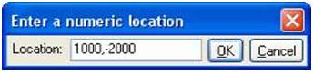
| To display the toolbar, initiate a command that requires you to pick positions, and then do one of the following: • Start entering the coordinates using the keyboard. • Click Tools > Enter a Numeric Location and select an option. To access additionaloptions, click Tools > Options > Shortcuts > Enter a Numeric Location. The following table explains the types of information you can enter. |
||||||||||||||||||||||||||||||||||||||||||||||||||
|
||||||||||||||||||||||||||||||||||||||||||||||||||
| After you enter the coordinates, press Enter or click OK to snap to the position. Snapping mode Tekla Structures has two snapping modes, relative and absolute. Use the variableXS_KEYIN_DEFAULT_MODE to indicate the default snapping mode. See also XS_KEYIN_ABSOLUTE_PREFIX Use the shortcut O (Tools > Ortho) to snap to positions in orthogonal directions on the work plane (0, 45, 90, 135, 180 degrees, etc.). To control orthogonal snapping, use the variables XS_SEMI_ORTHO_ANGLE andXS_USE_SEMI_ORTHO. For more information, see Appendix C, Variables, in the System Manual. |
||||||||||||||||||||||||||||||||||||||||||||||||||
| 178 TEKLA STRUCTURES 14.0 Settings and Tools | ||||||||||||||||||||||||||||||||||||||||||||||||||
 |
|||
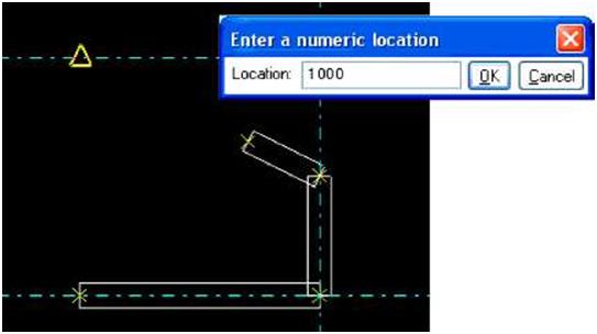
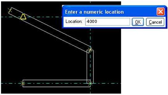
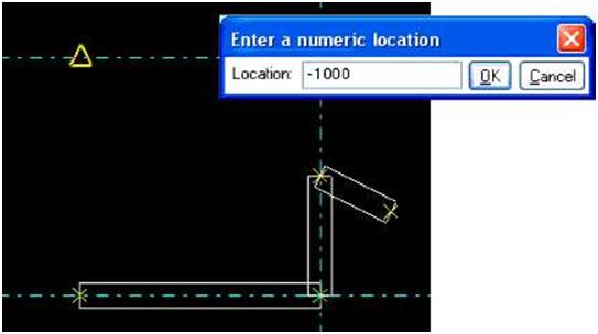
| You can also track beyond the snap point, for example, 4000 units from the last point picked. | |||
 |
|||
| Track in the opposite direction by entering a negative value, for example, -1000. | |||
 |
|||
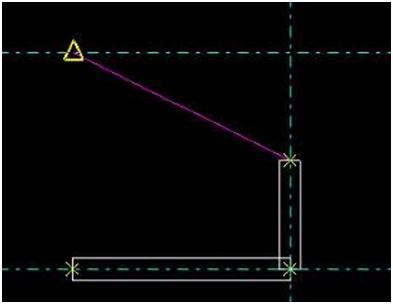
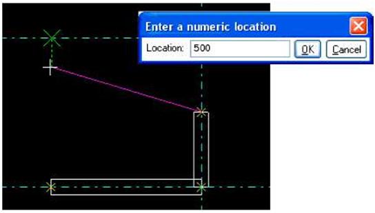
| Reference points |
In this example, we create a beam using a grid line midpoint as a temporary reference point and tracking along an orthogonal direction (shown as green dashed line) for 500 units. Click OK,and Tekla Structures creates the beam along the magenta line. |
||
| 180 TEKLA STRUCTURES 14.0 Settings and Tools | |||

| T | The 4D tool is included in the Project Management configuration only. | |||||||||||||||||||||||||||||||||||||||||||||
| Usage To use the project status visualization tool: 1. Click Tools > Project Status Visualization… to open the Project Status Visualizationdialog box. You have the following options: |
||||||||||||||||||||||||||||||||||||||||||||||
|
||||||||||||||||||||||||||||||||||||||||||||||
| 2. Select the object representation settings from the list box. 3. Select the Review date. 4. Enter the time step. |
||||||||||||||||||||||||||||||||||||||||||||||
| TEKLA STRUCTURES 14.0 187Settings and Tools | ||||||||||||||||||||||||||||||||||||||||||||||
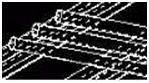
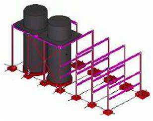
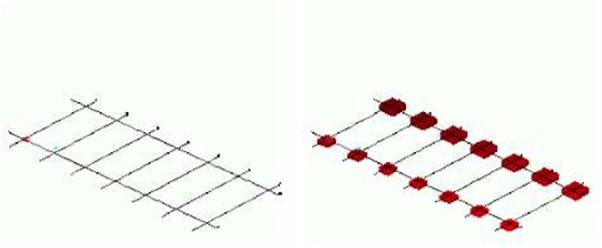
| 5. Select Scale start and Scale end. 6. Select the Refresh view automatically checkbox. 7. Click Save to save the properties. 8. Use project status visualization tool by clicking the step buttons. Project status visualization files Tekla Structures saves the project status visualization settings with filename extension *.4din the current model’s attributes folder. • You can copy the *.4d file to another model’s attributes folder. • To make the *.4d file available to all models, copy the file to the system folder. • Include also a copy of the object representation file (filename extension .rep) and object group files (filename extension .PObjGrp) when copying the *.4d file to theattributes or system folder to have all the files working correctly. Tekla Structures searches for the *.4d files in the standard search order. Project status visualization example In this example, we visualize when parts are erected. The project status visualization is based on object representation settings including an object group rule for the user-defined attribute Planned erection date. This is how the model looks with the standard object representation settings: |
||
 |
||
| Object To define which objects are shown in the model: representation 1. Click View > Representation > Object representation… to open Object representation settings dialog box. 2. Enter a name for the object representation settings. 3. Click Add row to add a new row. 4. Select the newly added row, and click Create new group… in the Object group list box. |
||
| 188 TEKLA STRUCTURES 14.0 Settings and Tools | ||
| 5. In the Object group – representation dialog box, enter a name for the group, for example, “plan_same_or_before_review_date”. 6. Click Save as. 7. Modify the rule. This rule should include all objects that have the user-defined attributePlanned erection date earlier than or equal to the review date. • Select Object in the Category column. • Select Planned erection date in the Property column. • Select Earlier than or equal in the Condition column. • Click Select date… in the Value list box and select Review date in the Select datedialog box and click OK. 8. Save the object group and click Close. 9. In the Object representation dialog box, select Color by class for the new object groupin the Color list box and check that the row is set to Visible. |
||
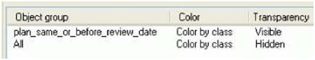
| 10. Set the All object group to last, and select Hidden: | ||
 |
||
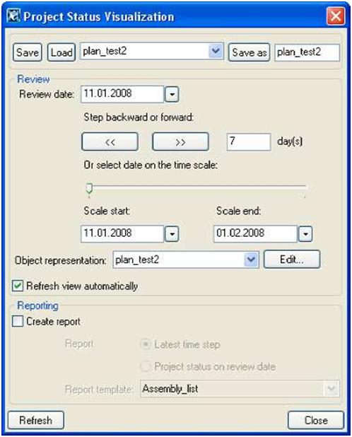
| 11. Click Save. Project status To use the object representation settings in the project status visualization tool: visualization 1. Click Tools > Project Status Visualization… to open the Project Status Visualization dialog box. 2. Modify the properties (the image below shows the Review date and other properties according to this example): |
||
| TEKLA STRUCTURES 14.0 189Settings and Tools | ||
 |
||||
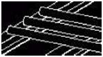
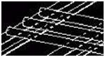
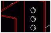
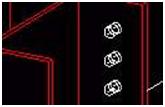
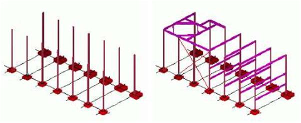
| 3. Click the step buttons to change the Review date and to view the changes in the model. The images below show how the objects are shown when you click the step button. The object group rule defines the visibility of the objects based to the time steps: |
||||
| Review date 01/11/2006 | Review date 01/18/2006 | |||
 |
||||
| Review date 01/25/2006 | Review date 02/01/2006 | ||||||||||||||||||||||||||||||||
 |
|||||||||||||||||||||||||||||||||
| Screenshot | |||||||||||||||||||||||||||||||||
| Function keys | Use Screenshot to capture dialog boxes, views, or the entire Tekla Structures window. Tekla Structures saves the screenshot as a bitmap in the current model folder. This can be a useful tool. You can use screenshots in posters, brochures, or other material to show projects carried out using Tekla Structures. Tekla Structures technical support staff may ask you for a screenshot if you contact them with a question. Use the following function keys to create screenshots: |
||||||||||||||||||||||||||||||||
|
|||||||||||||||||||||||||||||||||
| Print screenshot | Select the Tools > Screenshot > Print Screenshot switch to have Tekla Structures automatically print out the screenshot. If you need high resolution screenshots, use the command Tools > Screenshot > Custom….Tekla Structures opens a dialog box where you can define the properties of a screenshot, as follows: • From which view to take the screenshot • Filename • Include or omit view borders • DPI, size, background color, line properties (only for rendered views |
||||||||||||||||||||||||||||||||