
- GENERAL OVERVIEW
- CIVIL DRAWINGS
- ARCHITECTURAL DRAWINGS
- STRUCTURAL DRAWINGS
- MECHANICAL DRAWINGS
- PLUMBING DRAWINGS
- ELECTRICAL DRAWINGS
- MISCELLANEOUS DRAWINGS
GENERAL OVERVIEW
For identification purposes, drawings associated with construction and the building trades can be categorized into four main types, preliminary drawings, presentation drawings, working drawings, and shop drawings.
Preliminary Drawings
These drawings are essentially intended to be concept design explorations and means of communication between the architect and the client. They are not intended to be used for construction but rather to interpret the client’s needs and instructions, prepare functional studies, select materials, estimate preliminary costs, and solicit preliminary approval by civil authorities. They also form the basis for the final working drawings.
Presentation Drawings
These drawings are selling tools and normally consist of perspective views based on the preliminary design concept of the project. Presentation drawings are drawn to highlight the aesthetic qualities of a project and, in addition to perspectives, may include isometrics, colored elevations, and colored floor plans (Figure 6.1).
Construction or Working Drawings
The term “construction drawing” is generic in that it includes all the drawings needed by the various tradespeople to complete a building project. These drawings are prepared by the architect, engineer, and other specialists depending on the complexity of the project. Construction drawings are technical directions in graphic form, showing the size, quantity, location, and relationships of the building’s components.
In construction drawings as much information as possible is presented graphically, or by means of pictures. Most construction drawings consist of orthographic views. General drawings consist of plans and elevations drawn at a relatively small scale. Detail drawings (discussed later in this chapter) consist of sections and details drawn at a relatively large scale. A plan view is a view of an object or area as it would appear if projected onto a horizontal plane passed through or held above the object area. The most common construction plans are plot plans (also called site plans), foundation plans, floor plans, and framing plans. A plot plan shows the contours, boundaries, roads, utilities, trees, structures, and other significant physical features on their sites. The locations of the proposed structures are indicated by appropriate outlines or floor plans. As an example, a plot may locate the corners of a proposed structure at a given distance from a reference or base line. Since the reference or base line can be located at the site, the plot plan provides essential data for those who will lay out the building lines. The plot can also have contour lines that show the elevations of existing and proposed earth surfaces and provide essential data for the graders and excavators.
The main functions of construction drawings include:
- Instruments for material take-offs: Labor, material, and equipment estimates are made from working drawings prior to construction.
- Instructions for construction: Working drawings show specific sizes, location, and relationships among all materials.
- Means for granting a building permit: Before construction can begin, the local building authority must review the working drawings to see that they meet the requirements of public safety in terms of structural soundness, fire, and other hazards. A building permit is issued to the builder only after approval of the drawings.
- Instruments for competitive bidding: In a free-enterprise system, working drawings allow potential contractors a uniform guide for preparing bids, thereby providing the owner with the most economical costs.
- Means of coordinating among the various trades: Working drawings are the basis of agreement between material suppliers and specialized trades.
- A permanent record for future remodeling or expansion or for legal use in the advent of a dispute: Working drawings eliminate remeasurements in case of future reconstruction. Drawings must be furnished in case of legal disputes. Building failures might possibly occur by natural, unavoidable causes, design errors, or neglect, but the drawings and design calculations are used as evidence and should be available for the life of the building.
- Basis for agreement between owner and tenant: In leasing all or portions of a building, the owner must use the working drawings in the contract agreement.
- A complement to the specifications: In obtaining written information from the specifications, contractors need the working drawings for interpretation. Information from one source is incomplete without the other.
Shop Drawings
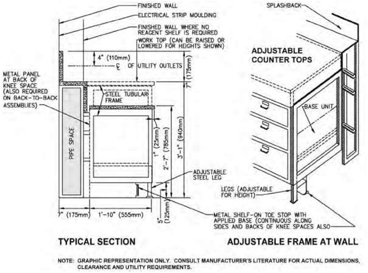
These are technical drawings prepared by various suppliers participating in the construction. On many jobs the architect or designer must rely on specialists to furnish precise information about the components. For example, if complex cabinetwork is required, it must be built to exact sizes and specifications.
A shop drawing is needed to ensure that it will fit into the structure and that the structure will accommodate it. Approval of the shop drawings usually precedes the actual fabrication of the components. With shop drawings the architect or designer is able to check the quantity of other components that subcontractors propose to furnish.
The Construction Drawings Set
The transition from approved preliminary design/concept drawings to full-blown construction documents is very significant because it signifies the completion of one phase—that of making design decisions—and the beginning of a new phase—the production of construction documents, which is essential to the implementation of the project.
Construction drawings are sometimes referred to as “working drawings” or “production drawings.” These drawings provide all the required information, both graphic and written, about the project. The information provided will be specific to every aspect of the proposed project. Preparing construction drawings represents the final step in the design process. The completed drawings become a “set” incorporating all the odifications made by the designer during the process of transition from the schematic-design to the working-drawings phase. Included in the construction drawing set will be detailed information regarding the building envelope, structural and mechanical systems, furniture, equipment, lighting, outlets, demolition, and so on. This information is explained through floor plans, interior or exterior elevations and sections, mechanical and electrical drawings, and detail drawings. Detailed specifications are also typically included.
The construction drawings and specifications are also used for pricing the project. Two or more general contractors are usually provided with the same set of documents to bid on. This facilitates fairness in that each contractor shares the same information and no one has any more or less information than his or her counterpart has when pricing.
Building Permits
The completed blueprints must also be submitted to the local building department to ensure that the proposed design is in compliance with all regulatory agency requirements, including those set by the zoning, fire, health, and other departments. A building permit will only be issued after the drawings are checked and approved by the various departments.
Almost all new construction (commercial, civic, industrial, residential, etc.) and renovation require a building permit. In order to obtain a permit, a complete set of construction drawings is required. Only in the case of minor changes to an existing building will a permit not be required. Examples of minor changes would include minor repair or painting. For residential projects, such as a renovation or addition to an existing building, a building permit will be required. All structural work must comply with applicable code standards.
A building permit is a document that states that approval from the local building department has been given to proceed with construction or demolition. This document is numbered and recorded at the local building department. The permit(s) must be posted in a visible location on the construction site. It is unlawful to start construction or demolition before a permit is issued. This document is necessary for all new construction, additions or renovations of both residential and commercial projects. An application is made at the building department in the city, town, or municipality in which the work is to take place.
A complete set of construction documents can be large—30 or more drawings, or small—10 to 15 drawings—depending on the size and type of project. A shopping mall would require many drawings, whereas a small residence would require fewer. Today almost all construction drawings are produced on computers. One reason is that CAD software is faster and results in greater drawing accuracy, consistency, correctability, and easier storage.
Construction drawings are considered to be legal documents, and everyone involved in the project— owner, architect/engineer, and general contractor—all use these drawings as their source of information. But in order to produce a comprehensive set of construction drawings, knowledge of design and building methods are necessary.
The types of drawings discussed in this chapter are essentially construction drawings, including architectural drawings, structural drawings, mechanical drawings, electrical diagrams, details, and shop drawings. Construction drawing is any drawing that furnishes the information required by the craftspeople to rough in equipment or erect a structure.
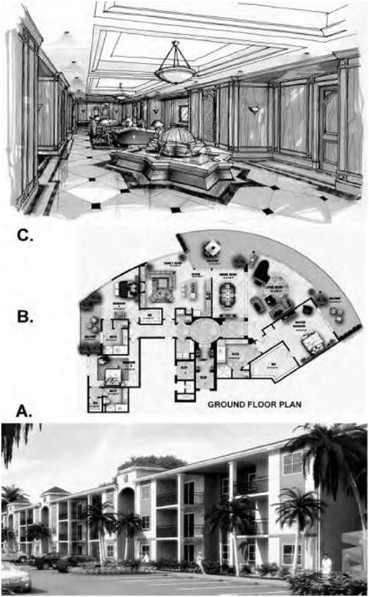
Ltd.). C. Hand-drawn office-lobby interior with mahogany paneling (source: Kubba Design).
Cover Sheet
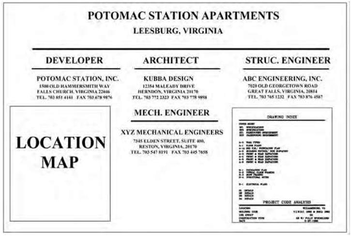
The first sheet in a set of working drawings is the cover sheet (Figure 6.2). This sheet is important because it lists the drawings that comprise the set (a drawing index) in the order that they appear. It normally lists the specific requirements of the building code having jurisdiction over the design of the project. A cover sheet should also list the project name and location, building permit information, key plan, and general notes. Names and contact information of all consultants should also be included. Other important information required includes the total square footage of the structure, the use group the structure will fall under, and the type of construction. Another important element on the cover sheet is the list of abbreviations or graphic symbols used in the set. Usually there is a section that contains general notes for the contractor, such as “Do not scale” or “All dimensions to be verified on site.”
With larger projects, a second cover sheet is sometimes included that includes information not shown on the main cover sheet. Likewise, a location map is sometimes included to locate the project site in relation to nearby towns or highways.
Information presented in a set of working drawings, along with the specifications, should be complete so the craftspeople who use them will require no further information. Working drawings show the size, quantity, location, and relationship of the building parts. Generally, working drawings may be divided into three main categories: architectural, mechanical, and electrical. Regardless of the category, working drawings serve several functions.
They provide a basis for making material, labor, and equipment estimates before construction starts. They give instructions for construction, showing the sites and locations of the various parts. They provide a means of coordination between the different ratings. They complement the specifications; one source of information is incomplete without the other when drawings are used for construction work.
CIVIL DRAWINGS
The most obvious difference between civil and architectural drawings is the use of the engineer’s scale.
Like architectural drawings, civil drawings include symbols and graphics that convey intent with a minimum of words. Some of the symbols and graphics are unique to site plans, and others are very similar to those used on architectural plans. Some civil drawings offer a legend to decipher the symbols and graphics on a specific set of drawings. Site plans often contain several sheets, depending on the size and complexity of the project. They are usually numbered starting with a “C,” such as sheet C-1, C-2, and so on. The term “site” is synonymous with plot or lot.
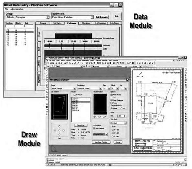
The calculations that are required for submission on a plot plan are not complex. What is needed is a basic understanding of what you are calculating and why. Moreover, as mentioned earlier in the chapter, most drawings and calculations today are easily generated with the use of computers. Figure 6.3 is an example of a simple computer-generated site plan using AutoCAD software.
There are four basic calculations required for the plot plan: site area (lot size), lot coverage (bird’seye view expressed as a percentage of the lot), gross floor area (combined size of parts of the structure), and floor-area ratio (FAR), a ratio of floor area to property size.
Site Plan
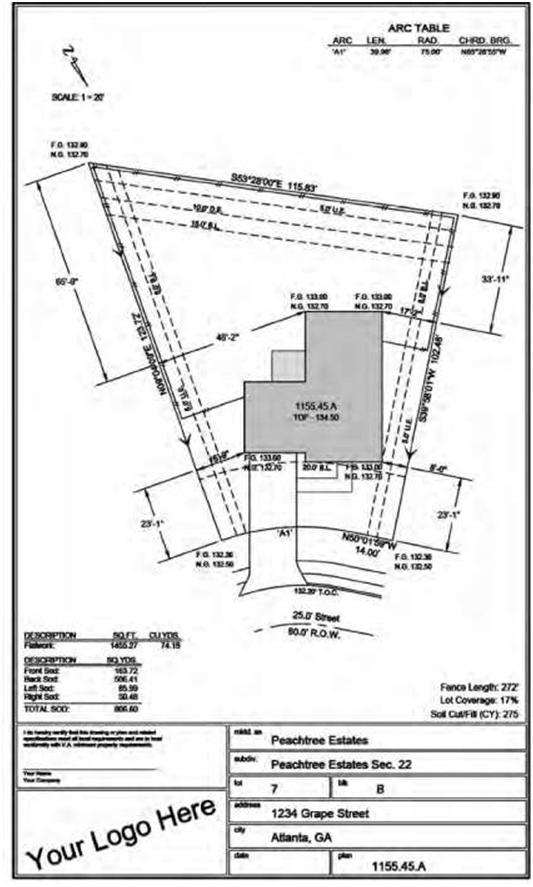
A site or plot plan is a scale drawing of a property that shows its size and configuration including the size and location of man-made features such as buildings, driveways, and walkways on the property. Plot plans show both what currently exists and what improvements are proposed (Figure 6.4). The main function of a basic site or plot plan is to determine the placement of the structure as it sits in reference to the boundaries of the construction site. Site plans clearly establish the building’s dimensions, usually by the
foundation’s size and the distances to the respective property lines. Setback dimensions are shown in feet and hundredths of a foot, as opposed to feet and inches on architectural drawings. Thus, an architectural dimension reading 40 feet, 6 inches would be 40.5 feet on a site plan.
A site plan includes not only the project but also the surrounding area. Site plans should outline location of utility services, setback requirements, and easements. Topographical data is also sometimes indicated, specifying the slope of the terrain. The grades at fixed points are shown throughout the area to show the land slope before construction is started and the finished grade after construction is completed.
Site plans are often required to accompany most applications in conjunction with a site-plan review submitted to the city or county in order to change how a particular property is used. For example, they are required for:
• Preapplication review of conceptual elements of multifamily, commercial, and industrial development
• Conditional-use permits
• Variances to zoning requirements
• Construction of new structures requiring a building permit
• A change of zone or a special zoning exception
A site plan should typically include:
• Legal description of the property based on a survey.
• Drawing scale: The site plan should be drawn to the most appropriate scale, for example, 1 inch = 10 feet,1 inch = 20 feet, or 1/4 inch = 1 foot.
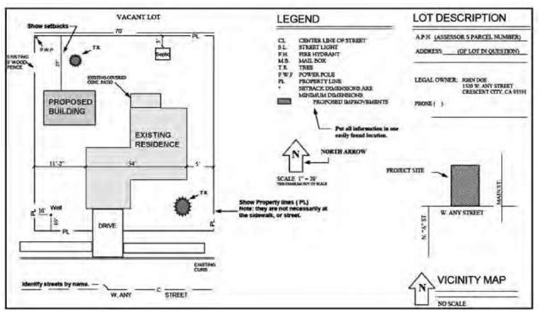
arrow, legal description, and vicinity map.
An arrow indicating north, usually towards the top right-hand corner of the sheet.
• Property-line bearings and directions: For most additions, property lines need to be physically
located. In many cases, a certificate of survey, signed by a licensed surveyor, is required.
• The distance between buildings and between buildings and property lines.
• The dimensions of the existing buildings.
• Location of adjacent streets and any easements.
• A clear indication of any proposed addition or alteration.
• Utilities.
• Other information that is relevant to the project.
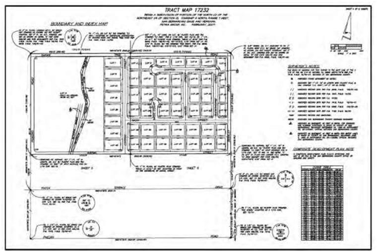
Plat Map
A plat is a map drawn to scale (usually supplied by a land surveyor or civil engineer) of part of a city or township showing some specific area, such as a subdivision made up of several individual lots. A plat will often consist of many sites or plots. A plat delineates the divisions of a piece of land (property-line bearings, dimensions, streets, and existing easements) and represents the first of several stages in a site’s development (Figure 6.5). City, town, or village plats chart subdivisions into blocks with streets and alleys. For additional clarification the blocks are split into individual lots, usually for the purpose of selling the described lots, usually termed subdivisions. In order for plats to become legally binding, they must be filed in local jurisdictions, such as a public-works department, urban-planning commission, or zoning board, which must typically review and approve them. Legal descriptions become part of the public record and can be reviewed at any time.
There are three basic types of legal descriptions:
- Metes and bounds: This is a system that identifies a property by describing the shape and boundary dimensions of a unit of land using bearing angles and distances starting from a defined point of origin. The point of origin may be referenced to the corner of some section or quarter-section described by the rectangular survey system. The metes are measured in feet, yards, rods, or surveyor’s chains. These legal descriptions are frequently used to describe land that is not located in a recorded subdivision.
- Rectangular survey system: This system provides for a unit of land approximately 24 miles square, bounded by a baseline running east and west and a meridian running north and south.
- This 24-mile square is further divided into 6-mile squares called townships. A range is an east and west row of townships between two meridian lines 6 miles apart. A township is divided into 36 numbered sections, each 1 mile square. Farm, ranch, and undeveloped land is often described by this method.
- Lot and block: This system is commonly used in many urban communities to legally describe small units of land because of its simplicity and convenience. A map is created in which a larger unit of land is subdivided into smaller units for the purpose of sale. The map is recorded after each lot has been surveyed by a metes-and-bounds description. Deeds then need only refer to the lot, block, and map book designation in order to describe the property. It is not necessary to state the survey bearings and distances or the rectangular survey description in the deed.
- Lot lines are laid out by polar coordinates: that is, each line is described by its length plus the angle relative to true north or south. This is accomplished by the use of compass direction in degrees, minutes, and seconds. The lot line may read N6o 49′ 29″ W. The compass is divided into four quadrants, NW, NE, SW, and SE.
There are many reasons to plat: - To designate roads and other rights of way
- To make sure that all property has access to a public right of way
- To create or vacate easements
- To dedicate land for other public uses, such as parks or areas needed for flood protection
- To ensure compliance with zoning
Demolition Plan
Many projects will be constructed on sites with existing features or exterior or interior elements that are not envisaged to be part of the final design. These will need to be removed or demolished prior to grad
ing for construction and are shown on a demolition plan. Figure 6.5 is an example of a demolition plan for interior elements of a house. It shows the elements to be demolished and to be retained. Trees and other items that are to remain should be noted in the keynotes. Dotted lines indicate items (walls, fixtures, etc.) to be removed to make the space ready for the new design. A keynote legend is usually included on a emolition drawing sheet, showing each number and corresponding note.
Topography Map
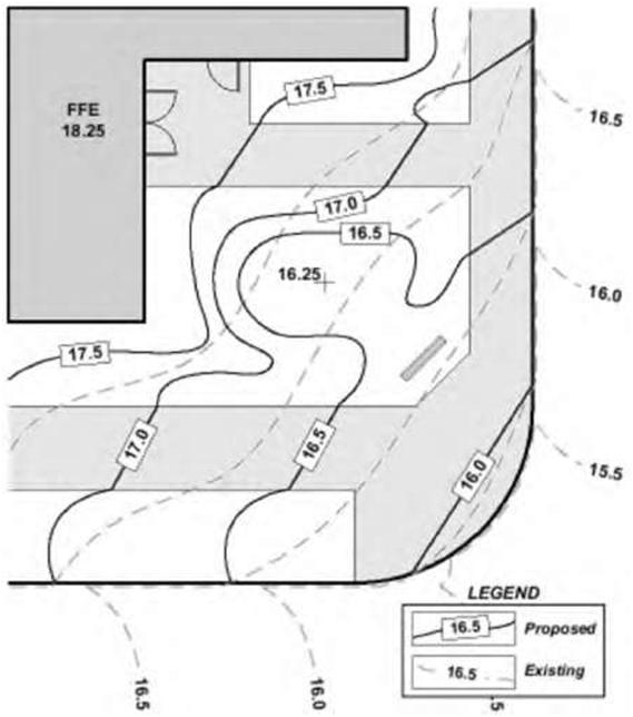
The other important function of the site plan is to highlight the special surface conditions, or topography, of the lot. This will indicate to the builder the slope or flatness of the site. The topography of a particular lot may be indicated on the site plan (Figure 6.6). For some projects the topography needs to be shown separately for clarity, and a grading plan has to be used. Topographical information includes changes in the site’s elevation, such as slopes, hills, valleys, and other variations in the surface. These changes in the surface conditions are shown on a site plan by means of a contour, which consists of a line connecting points of equal elevation. An elevation is a distance above or below a known point of reference, called a datum. This datum could be sea level or an arbitrary benchmark established for the particular project.
Architects normally adjust the existing contours of a site to accommodate the building construction and site-improvement requirements. Adjusting existing contours is one of the stages in the site-improvement process, in which the architect or designer requires a topography map to study the slope conditions that may impact the design. This map is usually prepared by a civil engineer and is meant to show in drawing form the existing contour lines and their accompanying numerical elevations. Normally, existing contour lines are illustrated by a dashed line, and new or proposed contours are normally shown as a solid line. The topography map can therefore be considered to be a plat map in which its broken lines and numbers indicate the grades, elevations, and contours of the site. The distance between the contour lines is at a constant vertical increment, or interval. Typically, an interval of five feet is used, but other intervals may be substituted, and one-foot intervals are not uncommon for site plans requiring greater detail (or where the change in elevation is more dramatic).
When reading a site plan, note that contours are continuous and often enclose large areas in comparison to the size of the building lot. This is why contours are often drawn from one edge to the other edge of the site plan. Contours do not intersect or merge except in the case of a vertical wall or plane.
For example, a retaining wall shown in plan view would show two contours touching, and a cliff that verhangs would be the intersection of the contours. When contour lines are spaced far apart, the land is relatively flat or gently sloping. When the contour lines are close together, the land is much steeper. A benchmark is normally required, which is basically a known reference point such as an elevation on the construction site. The benchmark is established in reference to the datum and is commonly noted on the site print with a physical description and its elevation relative to the datum. For example, “Northeast corner of catch basin rim – elev.1085’” might be found on a site plan. When individual elevations or grades are required for other site features, they are noted with a “+” and the grade. Grades differ from contours in that a grade registers accuracy to two decimal places, whereas a contour is shown as a whole number. A grading plan shows existing and proposed topography (Figure 6.7) and is used to delineate elevations and drainage patterns. Grading-plan requirements will vary from one location to the next, but a final grading plan will typically show the site boundaries, existing landform contours with a benchmark, existing site features, and proposed site structures. In some instances the grading plan may also show a cross section through the site at specified intervals or locations to more fully evaluate the surface topography.
The north arrow is used to show the direction of magnetic north as a reference for naming particular sides or areas of the project. Moreover, surveyors label the property lines in accordance with the directions normally found on a compass. This reference, in the form of an angle and its corresponding distance, is called the bearing of a line. The bearings of the encompassing property lines often provide the legal description of the building lot. Larger projects usually need several site plans to show the different scopes of related or similar work including drainage, utility plans, and landscaping plans.
ARCHITECTURAL DRAWINGS
Architectural drawings contain required information on the size, material, and makeup of all main members of the structure, as well as their relative position and method of connection. In essence, they consist of all the drawings that describe the structural members of the building and their relationship to each other, including foundation plans, floor plans, framing plans, elevations, sections, millwork, details, schedules, and bills of materials. Architectural drawings are generally numbered sequentially with the prefix “A” for architectural.
The number of architectural drawings needed to effectively convey the scope of a construction contract and satisfactorily implement a project is determined by such factors as the size and nature of the structure and the complexity of operations. General plans consist of plan views, elevations, and sections of the structure and its various parts. The amount of information required determines the number and location of sections and elevations.
Plans
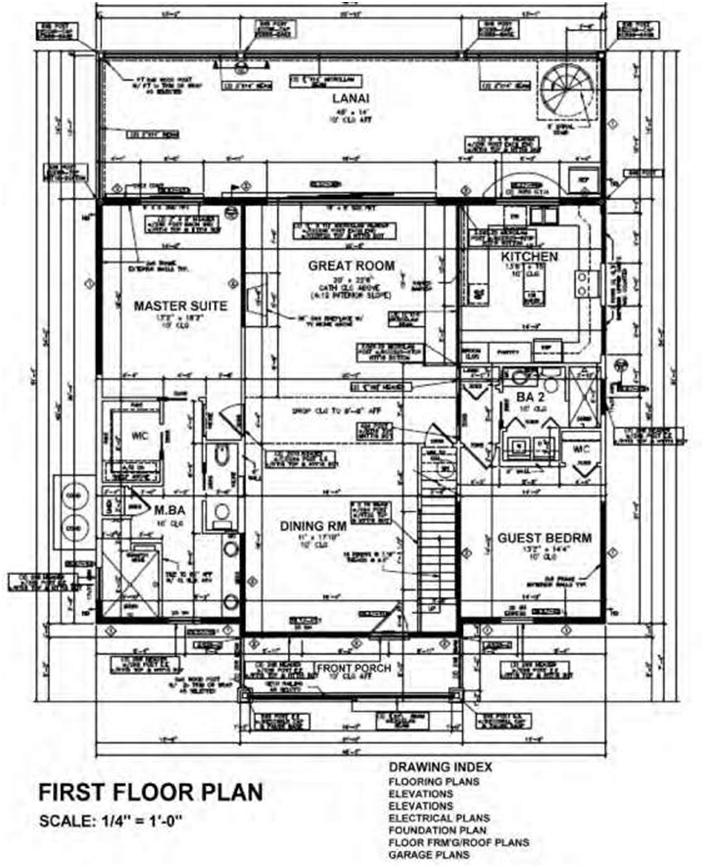
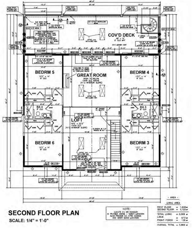
A plan is actually a part of the architectural drawing that represents a view of the project from above. The floor plan is the most common type of plan view. A floor plan is a two-dimensional view of a space, such as a room or building. It is a view of the space from above, as if the space were cut through horizontally at the windowsill level with the upper half removed. You are looking down at the floor. In general, a floor plan’s main function is to identify and delineate the use of space. It identifies the locations and sizes of components such as rooms, bathrooms, doors, windows, stairs, elevators, means of egress, and room access (Figure 6.11). The floor plan will also show the locations of walls, partitions, doors, washrooms, and built-in furniture as well as dimensions and other pertinent information. When too much information is shown on a single plan, it becomes confusing, which is why very often, especially for complex projects, several different plans are required. These additional drawings may include demolition, partition, fixture, and floor-finish plans.
Architectural plans, when part of a working-drawing set, should be dimensioned to show actual length and width, thereby allowing the reader to calculate areas. Dimensions should be accurate, clear, and complete, showing both exterior and interior measurements of the space. For minor projects, a separate set of specifications is not always issued, depending on the financial constraints and on the assumption that the notes will suffice.
Plans are typically drawn to scale. The most common scales for floor plans (depending on size of project) are one-eighth inch = one foot (scale: 1/8 inch = 1 foot, 0 inches) and one-quarter inch = one foot (scale: 1/4 inch = 1 foot, 0 inches). The plan scale should always be noted on the drawing.
Elevations
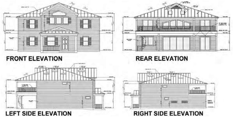
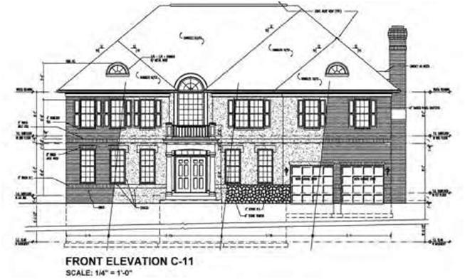
Elevations are an important component of the construction-drawing set and the design and drafting process. Elevations are essentially views that show the exterior (or interior) of a building. They represent orthographic views of an interior or exterior wall. They are basically flat, two-dimensional views with only the height and width obvious. Exterior elevations provide a pictorial view of the exterior walls of a structure and indicate the material used (stone, stucco, brick, vinyl, etc.), the location of windows and doors, the roof slopes, and other elements visible from the exterior. Elevations are usually identified based on their location with respect to the headings of a compass (north, south, east, and west elevations). Alternatively, they may be labeled front, rear, right, and left elevations (Figure 6.12A). Four elevations are normally required to show the features of a building unless the building is of irregular shape, in which case additional elevations may be required.
The main function of exterior elevations is to provide a clear depiction of the façade treatment of the building and any changes in the surface materials within the plane of the elevation. They also show the location of exterior doors and windows (often using numbers or letters in circles to show types that correspond to information provided in the door and window schedule).
Elevations are typically drawn to the same scale as the floor plan. The scale of the elevation is noted either under or to the side of the title of the elevation or in the title block (Figure 6.12B). A common scale is one-quarter inch = one foot (scale: 1/4 inch = 1 foot, 0 inch), although a scale of one-eighth inch = one foot (scale: 1/8 inch = 1 foot, 0 inches) is used for larger buildings.
While floor plans show horizontal measurements of elements, elevations mainly provide vertical measurements with respect to a horizontal plane. These dimensions provide a vertical location of floorto-floor heights, windowsill or head heights, floor-to-plate heights, roof heights, or a variety of dimensions from a fixed horizontal surface. These measurements can be used to calculate quantities of materials
required. Sometimes the elevation dimensions are given as decimals (7.5 feet as opposed to 7 feet, 6 inches). Along with the dimensions on the elevations, notes are included to supplement and clarify information in a floor plan. In general, dimensions are usually kept to a minimum on elevations. Most consultants use elevations to depict sizes of major components, with the majority of dimensions placed on the sections, which provide greater clarity regarding construction materials and methods.
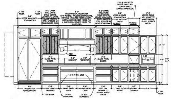
Interior elevations show the inside walls of a space. Figure 6.12C shows a kitchen elevation. Notice that the annotations take the form of specifications and are written at their appropriate location and not as notes to the side.
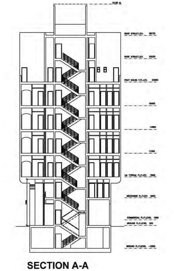
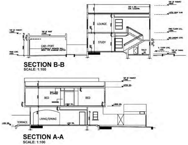
Sections
Sections are usually used to clarify the building design and construction process. Transverse and longitudinal sections are usually drawn at the same scale as the floor plan and show views of cross sections cut by vertical planes. A floor plan or foundation plan, cut by a horizontal plane, is a section as well as a plan view, but it is seldom called a section. They offer a view through a part of the structure not found on other drawings. To show as much construction information as possible, it is not uncommon for staggered (offset) cutting planes to be used in developing sections. To reduce the time and effort required for drafting and to simplify the construction drawings, it is common practice to use typical sections where exact duplications would otherwise occur.
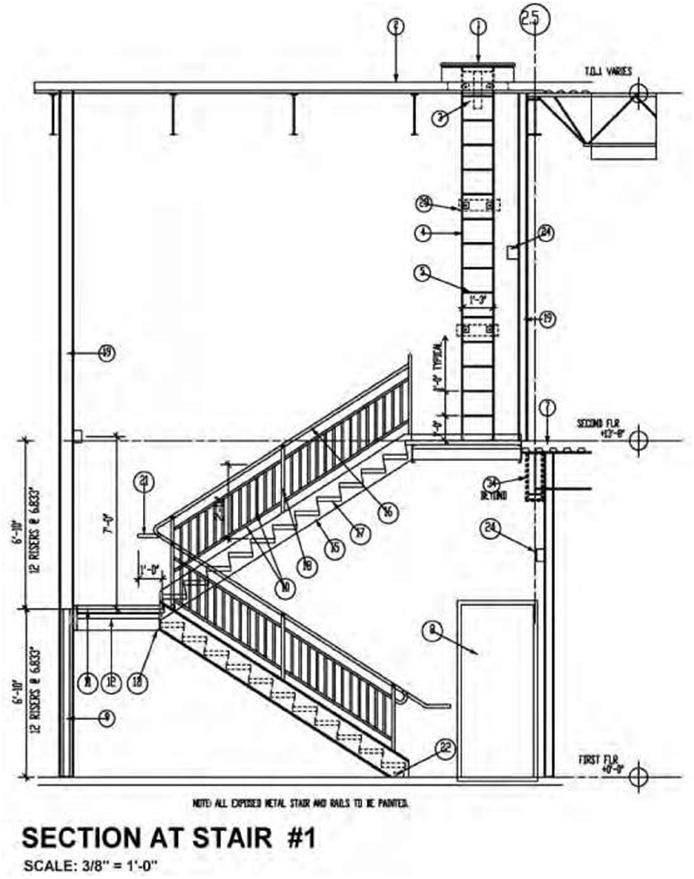
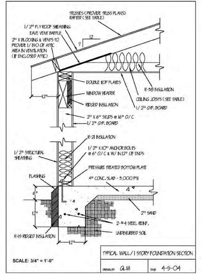
Examples of building sections can be seen in Figures 6.13A and B. Figure 6.14A represents a section through a staircase drawn to a 3/8 inch = 1 foot, 0 inches scale. Several different sections may be incorporated into the drawings. Sections taken from a plan view are called cross-sections; those taken from an elevation are referred to as longitudinal or simply wall sections. Figure 6.14B shows a typical wall section. This type of section is commonly drawn at a scale of 3/4 inch = 1 foot, 0 inches. It is normally located in the structural division and provides information that is necessary to understand the structural arrangement, construction methods, and material composition of the walls of the building. Using sections in conjunction with floor plans and elevations allows the reader to get a better understanding of the project and how it is put together.
Sections are used as needed in each of the main divisions of construction drawings to show the types of construction required, the types and locations of materials used, and the method of assembling the building parts. Although they may be used in each of the divisions, the most common are the architectural and structural divisions. All sections are important to those responsible for constructing a building.
STRUCTURAL DRAWINGS
The structural drawings provide the reader with a view of the structural members of the building and how they will support and transmit its loads to the ground. Structural drawings (often referred to as “struc-turals”) are sequentially numbered beginning with an “S,” as in S-1, S-2, S-3, etc. They are normally located after the architectural drawings in a set of working drawings. For new construction, structural-engineering drawings will be needed for foundation and footing details, the structural frame design, beam sizes, and connections. In concrete structures, the structural drawings will indicate concrete forming details, dimensions of members, and reinforcing-steel requirements. If the structure is steel-framed, the size and type of steel framing will be indicated.
The benefit of structural drawings is that they provide information that is useful and can stand alone for subtrades such as framers and erectors. The structural drawings clearly indicate main building members and how they relate to the interior and exterior finishes without providing information that is not necessary for this stage of construction.
Structural drawings, like architectural drawings, start with the foundation plans, ground or first-floor plan, upper-floor plans, and the roof plan. The main difference is that only information pertinent to the structural systems is shown. For example, a second-floor structural plan would show the wood or steel framing and the configuration and spacing of load-bearing members but not doors or non-load-bearing partitions. Following the plan views are the sections and details in the same basic format as in the architectural drawings. Schedules are used to record such information as footings, columns, and trusses.
Types of Foundations
Houses and small frame buildings do not need complicated foundation systems. A simple inverted-T
foundation is all that is normally needed to support the structure under normal conditions. Larger and
more complex buildings impose a heavier burden on the foundation system and need to be carefully designed by structural engineers. Foundations for large commercial buildings perform the same functions as those for light-frame structures. The main difference in the foundations for a commercial building and that for a small residence is often the thickness of the concrete and the amount of reinforcing steel.
Foundations are usually constructed of continuous footings, pilings, or grade beams. Continuous or spread foundations are commonly used in residential and light-commercial construction. This type of foundation is based on a footing and wall. Concrete footings form the base of the foundation system and are used to displace the building loads over the soil. Piling foundations are typically used when conventional trenching equipment cannot be used safely or economically. Piling is a form of foundation system that uses columns to support the loads of the structure. They are rarely used for residences or low-rise commercial buildings. Grade beams are reinforced-concrete beams positioned at grade (ground) level below the stem wall to provide a bearing surface for the superstructure. They can be used in place of the foundation to provide added support for a foundation in unstable soil.
Foundation Plan
A foundation plan (Figure 6.15) is a plan view of a structure projected onto an imaginary horizontal plane
passing through at the level of the top of the foundation. A foundation sheet will indicate the size, thickness, and elevation of footings (footers), with notes regarding the placement of reinforcing bars (rebars).
It will typically note locations for anchor bolts or weld-plate imbeds for structural steel and other elements. The footing schedule is normally found on the first sheet of the structural notes, which also includes notes regarding the reinforcing requirements and other written statements for structural strengths and testing requirements. To be able to properly interpret a foundation plan, you must first view the other plans, such as the sections and roofing plan.
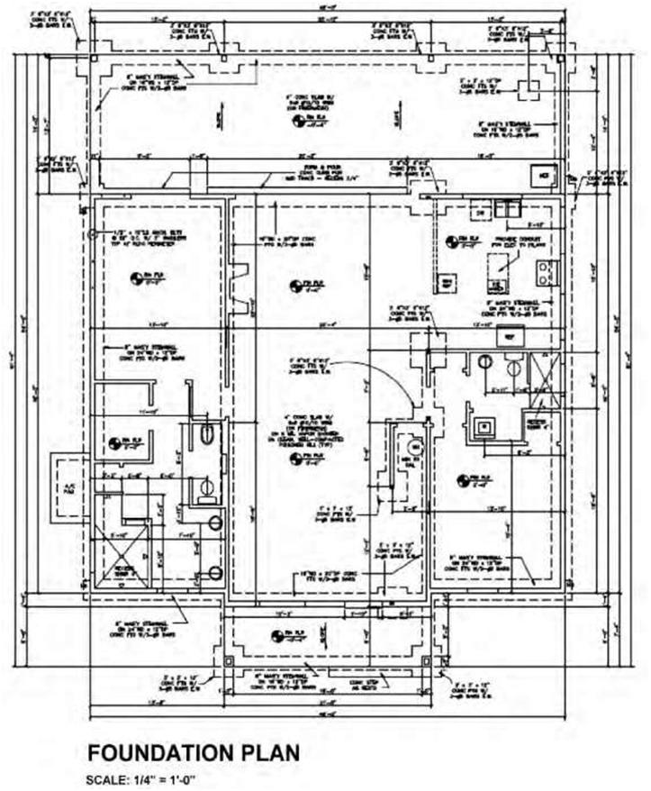
The foundation plan shown in Figure 6.15 tells you that the main foundation of this structure will consist of an 8-inch masonry stem wall, centered on a 24-inch-wide by 12-inch-deep concrete footing reinforced with three #5 bars. The width and depth of the concrete footing will vary according to location.
The drawing also shows a 4-inch-thick concrete slab reinforced with welded wire mesh. Besides the outside wall and footing, there will be two 30-inch-, 36-inch-, or 40-inch-square concrete footings reinforced with three #5 bars in each direction. From the drawing we can see that ½-inch-by-10-inch anchor bolts are used at 32-inch centers typically located on the building’s perimeter.
Framing Plan
The framing plan will indicate the material used for framing the building and may include wood or metal studs, concrete-masonry units, or structural steel. Framing drawings include the basic skeletal structure of the building and are drawn to scale. Floor-joist locations, walls, and roof trusses are part of the overall detail of these plans. Generally, locations of each stud are not included, since the process is standard. However in some cases there are instructions for particular wall-construction methods.
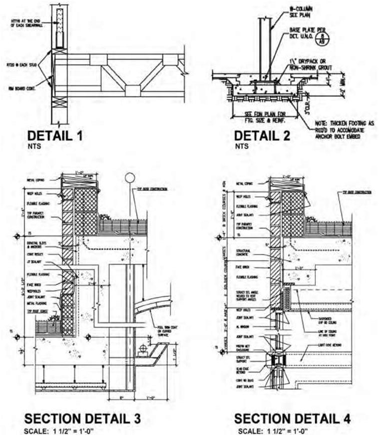
Intermediate structural framing plans are used for multistory construction, where each level may require support columns, beams, joists, decking, and other elements. Structural drawings also typically incorporate numerous details relating to the structure. Figure 6.16 shows typical examples of structural details.
MECHANICAL DRAWINGS
The cover sheet for mechanical drawings should contain appropriate notes, legends (chart or table of symbols and abbreviations), and details. The mechanical plan specifies the design of or the modifications to the mechanical system, ductwork layout and dimensions, mechanical equipment location, damper locations, design air-delivery rates, diffuser locations, thermostat locations, and supplemental cooling systems if required. Mechanical plans are normally identified as M-1, M-2, M-3, etc. Some consultants prefer the heating, ventilating, and air-conditioning drawings, commonly referred to as the HVAC drawings, to be sequentially numbered and prefixed by the letter “H”; the plumbing drawings to be prefixed by the letter “P”; and the fire-protection drawings to be prefixed by the letters “FP.” Most of the work shown on these types of drawings is in plan view. Because of the diagrammatic nature of mechanical drawings, the plan view offers the best illustration of the location and configuration of the work.
Due to the large amount of information required for mechanical work and the close proximity of piping, valves, and connections, the engineer utilizes a variety of symbols and abbreviations to convey the design intent. Examples of these symbols and their meaning can be found in Chapter 8.
Mechanical systems deal with the heating and cooling of buildings or spaces. The two primary methods of heating and cooling use air or water. In an all-air system hot or cold air is transported to the space with supply and return air ducts. A typical example is a residential forced-air furnace. The furnace uses gas or oil to heat the air. The air is forced through the ductwork by an electrically powered fan in the furnace. A separate air-conditioning unit is installed for cold air. For most commercial buildings, a large unit, often located on the roof, powers the all-air system. Supply-air ductwork, registers, and return-air grilles are required in all spaces within the building.
An all-water heating system uses a type of coil through which hot water is circulated. The most common example is the fin-tube radiator found in older homes, typically located in front of a window. Today the most common system is the radiant floor heating panel.
An all-electrical heating system uses electricity to heat elements within a radiator. The most common is the baseboard heater. It is used when a furnace is not installed. For example, many small cottages use baseboard heaters. Smaller, older commercial buildings rely on a baseboard installation. This system can also be found in larger commercial buildings as an addition to other systems. An electric radiator with a built-in fan might be located at an exterior entrance door to provide extra heat on the inside.
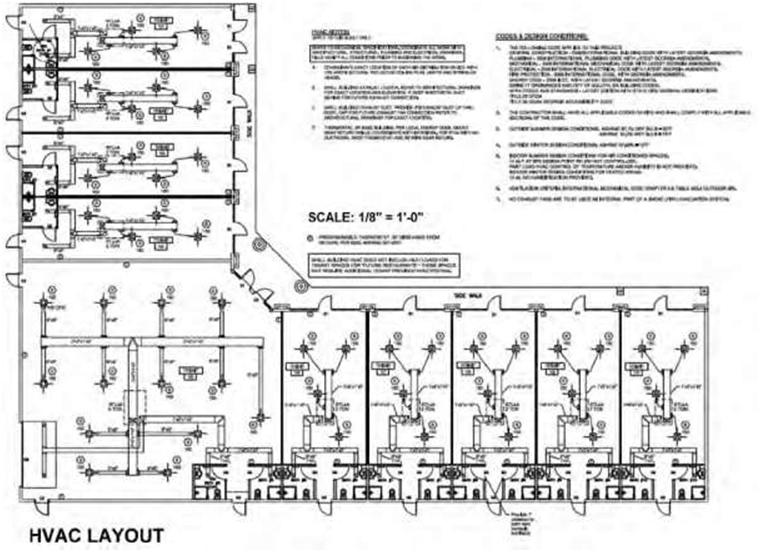
The mechanical drawings provide the client, the builder, and the permit department with the complete HVAC layout for the job. These drawings are typically part of the construction-drawing set. They are submitted with the construction drawings for a building-permit application (Figure 6.17). They are also part of the package for pricing the project. They are used for construction. All ducting, venting, exhaust fans, and heating and/or cooling units must be supplied and installed as per the approved drawings. A mechanical-engineering consultant produces the mechanical drawings. Often the same person or company will produce the electrical and plumbing drawings. These drawings must comply with the various building codes including all provincial and local codes.
Generally, the engineer uses these plans and incorporates his/her ducting layout. Diffusers, returnair grilles, and exhaust fans are drawn in as symbols. Heating and/or cooling systems are specified and their location indicated. Legends, schedules, details, and notes specific to the project are added.
On small projects, all information required is covered on one or two drawing sheets. For large or complex projects, many drawing pages are necessary to cover all areas of the project.
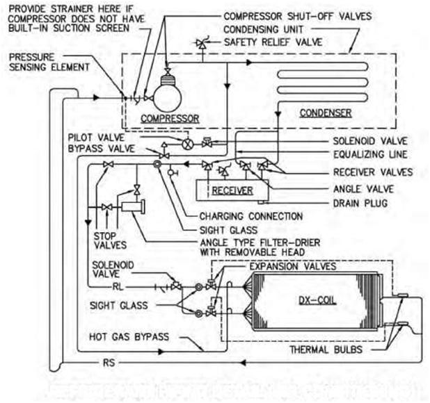
Typically, the engineer’s drawings must note the type, location, and number of heating and/or airconditioning units. HVAC and electrical connections are specified, as well as any connections to gas lines or water systems. The thermostat type, location, and number are also noted. Figure 6.18 shows a refrigerant-piping detail diagram Many projects require that heat-loss and heat-gain calculations be provided. Air-balancing information or air-distribution-device schedules are usually included. The information required depends on the type of project being built.
Many cities and towns have energy-conservation regulations. The engineer’s drawings must abide by all codes and bylaws pertaining to the city, town, or province where the project is located.
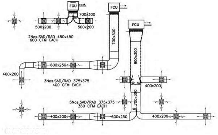
The following are typically included in a set of mechanical drawings:
• Plans showing the size, type, and layout of ducting
• Diffusers, heat registers, return-air grilles, and dampers
• Turning vanes and ductwork insulation
• HVAC unit types, quantities, and location
• Thermostat types, quantities, and location
• Electrical, water, or gas connections
• Ventilation and exhaust fans
• Symbol legend, general notes, and specific key notes
• Heating and/or cooling load summary
Other information, depending on the complexity of the project, may include:
• Connection to existing systems
• Demolition of part or all of existing systems
• Smoke detector and firestat for ducting
• Thermostat programming
• Heat-loss and heat-gain calculations per area
• Round-duct, turning-vane, and lay-in-diffuser details
• Special conditions, such as seismic restraint codes
Engineer’s drawings are required for all commercial projects involving HVAC work, including additions, renovations, or new construction. A permit is required prior to commencing any on-site work.
Drawings and permits are also needed for residential projects when any substantial work related to HVAC is to take place. For small projects, a licensed mechanical contractor can provide the information required to obtain a permit.
Concept and designs are the first stage of any project. When established, the next stage is construction drawings. Once the floor and reflected-ceiling plans are complete, they are passed to the engineer to produce the mechanical drawings. The engineer’s drawings become part of the construction drawing set.
PLUMBING DRAWINGS
Plumbing drawings provide all pertinent information on the design of the plumbing system for a project,
including line sizes and location, fixture location, isolation valves, storage-tank capacities, hot-waterheater capacities and locations, and drain locations and routing. Plumbing systems involve two major components, water supply and drainage. Water is supplied under pressure through pipes to plumbing fixtures. Drainage works by gravity: Drain pipes must slope downward. Vent pipes are required. A plumbing floor plan will typically show the location and type of plumbing fixtures, as well as the route pipes will be run (overhead or through walls) for potable water, drainage, waste, and vents. Plumbing drawings are usually numbered beginning with “P,” as in P-1, P-2, etc.
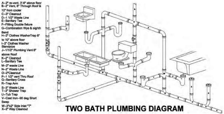
The first component connected to a fixture is a trap. Traps are located at every fixture. A trap is the u-shaped pipe found below a sink. Some traps are part of the design of the fixture and are not visible, as in a toilet or double sink. The trap catches and holds a small quantity of water to provide a seal. This seal prevents gases from the sewage system entering the building.
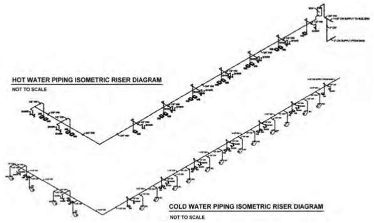
From the trap sewage travels through drainage pipes in branch lines to a vertical stack. A soil stack carries waste from toilets. A waste stack carries the other waste from a sink, washing machine, or dishwasher. All drainage pipes must be connected to vents. Vents are open to the outside air. Vents allow built-up sewage gases to escape and pressure in the system to equalize. Figure 6.19 shows a schematic isometric of a two-bath plumbing system and the various connections and outlets needed.
Plumbing drawings are typically part of the construction-drawing set. In most cases, they are submitted with the construction drawings for a building-permit application. They are also part of the package for pricing the project for the client. They are used for construction. All related plumbing lines; drains, connections, and vents must be installed according to the approved drawings.
A mechanical-engineering company produces the drawings. They must comply with the National Plumbing Code and with national, provincial, and local codes. Engineers produce their own drawings. They are based on plans provided by the interior designer or architect. These plans show the engineer the location of plumbing fixtures such as toilets, sinks, and water heaters in the design. Some projects require piping for equipment as well.
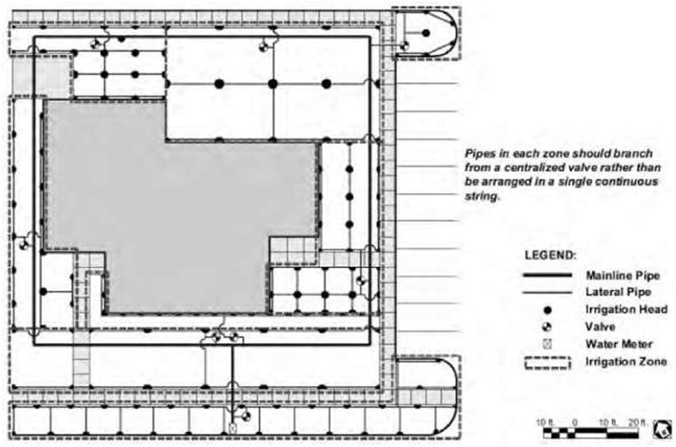
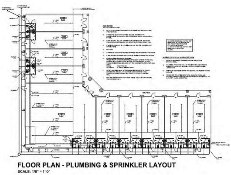
Generally, the engineer draws a plumbing plan and connection diagrams. Typical diagrams are of the water-supply system and the sanitary stack. Legends, schedules, and notes specific to the project are added. On small projects, there are usually only a few fixtures, a sink and a toilet. In this case, the required information is included on the mechanical-drawing sheets. For large or complex designs, the plan(s), diagrams, notes, etc., are on separate sheets. Several sheets may be required to cover all the information. Figure 6.20 shows a plumbing and sprinkler layout plan. The engineer’s drawings must provide information regarding the connections to the main water and sanitary sewer lines. The layout of any existing and new piping is indicated on the plan. The size for all lines for water, sanitary, and venting must be noted. The hookup to the water meter, new or existing, is covered, and the type, size, and location of the water heater are specified.
The following are typically included in a set of plumbing drawings:
• A plan with lines and symbols representing all piping
• Symbol legend, general notes, and specific key notes
• Fixture schedule, specifying the manufacturer and model for each item
• The sizes for all piping, cold/hot water, sanitary, vent lines, etc.
• Diagrams, such as water riser and sanitary stack
• Information regarding the water heater
Other information may be needed, depending on the complexity of the project:
• Details drawings, such as water heater, water-meter connection, or floor drains
• Diagrams or details referencing special equipment requirements
• Fire-protection notes
• Fire-sprinkler notes and symbols
• Special-air lines
• Natural-gas lines
Engineer’s drawings are required for all commercial projects involving any plumbing work. This applies to additions, renovations, or new construction. A permit is required prior to commencing any work on site.
Building codes specify the number of toilets, urinals, and lavatories required in a building or space, based on the occupancy type. In many cases the facilities must be designed as accessible for the disabled as discussed in Chapter 11. The designer, architect, and engineer must comply with all codes when producing their final drawings.
Drawings and permits are also needed for residential projects when substantial plumbing work is to take place. For small projects, a licensed plumber can submit the information required to obtain a permit.
A professional engineer also provides the required drawings and reports for a septic-tank installation. A sewage permit must be obtained. A septic tank is installed where a sanitary sewage connection to a municipal treatment facility is not possible.
Concept and designs are the first stage of any project. When established, the next stage is construction drawings. Once a floor plan is complete, it is passed over to the mechanical engineer to produce plumbing drawings. The drawings become part of the construction-drawing set.
In some residences and commercial structures, a separate plumbing plan is drawn to show fixtures,
water-supply and waste-disposal lines, equipment, and other supply and disposal sources. These isometric drawings are much easier to understand and are invaluable to those responsible for preparing material estimates and to the craftspeople responsible for installing plumbing systems. The mechanical division of a set of construction drawings will include, in addition to plumbing plans and details, drawings for any heating, ventilation, and air-conditioning systems that a building might contain. Frequently, the drawing sheets in the mechanical division are identified by the designating letter M in the title block. However, remember that in the order of drawings, sheets containing heating, ventilation, and air-conditioning drawings will precede those for plumbing.
ELECTRICAL DRAWINGS
The final group of working drawings is usually the electrical drawings. Architects usually hire electrical consultants to design the electrical services in buildings (unless they have electrical engineers within the firm). The electrical drawings show the various electrical and communication systems of the building, and they provide the client, the builder, and the permit department with the complete power layout for the project. The electrical cover sheet indicates all electrical specs, notes, and panel schedules. This sheet includes the specification of supplemental electrical panels if required. These drawings are typically part of the construction-drawing set. They typically include electrical power and lighting plans, telecommunications, and any specialized wiring systems such as fire or security alarms.
Electrical drawings show the location of electrical circuits, panel boxes, and fixtures throughout the building, as well as switchgears, subpanels, and transformers when they are incorporated in the building. The electrical drawings are submitted with the construction drawings for a building-permit application. In some cases, they are submitted separately to obtain an electrical permit. Electrical plans are normally numbered E-1, E-2, E-3, etc.
Power Plan
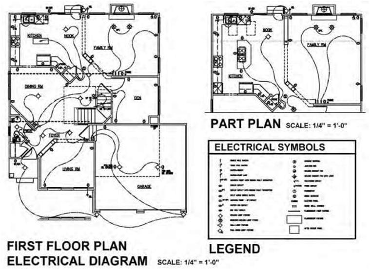
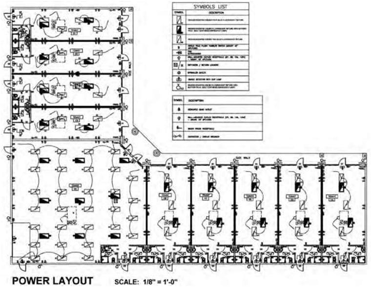
The power plan is a drawing of the floor plan showing all required outlets, locating panels, receptacles, and the circuitry of power-utilizing equipment and special systems. The designer or architect will often draw a power plan and dimension these locations. This is important to the engineer, especially if the connection must be at a specific location or height or if it is floor-mounted or mounted within a fixture. Figure 6.21 shows two examples of electrical layouts, one for a residence and the other for a commercial installation.
If a power plan is not provided, then the engineer draws it. This document indicates all outlets and circuitry, electrical-distribution system, riser location, routing of service, design voltage and amperage, and transformer size and location. It is an engineering drawing separate from the architectural set.
The engineer draws in the circuiting for every power receptacle. The circuit tie to the electrical panel is noted. A legend provides a description for each symbol used on the plan. Conduit size, special power specifications, and notes are included. A project with special equipment or systems requires additional legends, wiring schedules, or diagrams.
Electrical systems provide power for lighting, outlets, and equipment. The local power company supplies electricity to the building, including the meter. A licensed electrician can install an electrical panel of the appropriate type and size.
Circuit breakers in the panel trip off if a circuit is overloaded. It is often an indication that there is a problem with an appliance or other equipment or that too many items are plugged into one outlet source.
Outlets in wet areas must be grounded. Ground-fault-interrupter (GFI) outlets are required in bathrooms, kitchens, or outdoor areas.
Special power outlets, called dedicated circuits, are placed on their own circuit. They are used for sensitive equipment such as computers or equipment that requires voltage greater than 120 volts, including outlets for electric ranges, large copy machines, or other special equipment.
An electrical engineer designs the system for a commercial or large residential project. An electrical contractor can design the system for smaller residential projects. The drawings are part of the package for pricing the project for the client and are used for construction. The electrician must wire all outlets, lights, and panels according to the approved drawings.
The National Fire Protection Association publishes the National Electrical Code, which specifies the design of safe electrical systems. Electrical engineers and electricians should know this code, as it is an accepted standard for electrical installations. They should also be familiar with any state or local codes that apply.
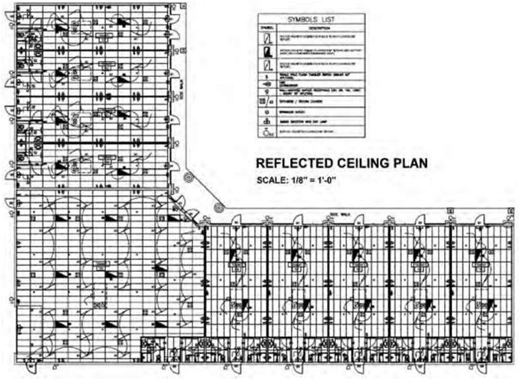
Reflected Ceiling Plan
A reflected ceiling plan (RCP) is a drawing of a room or space looking down at the interior ceiling. The designer or architect produces this plan to graphically show the ceiling treatment, ceiling grid, and the placement of all light fixtures as well as light fixtures to be relocated or removed. The plan indicates the type of ceiling (acoustical tile, gypsum board, etc) and the ceiling heights. The location of all light fixtures, speakers, special lighting, ceiling outlets, and switch locations is indicated and labeled. A ceiling-fixture legend is also normally included to provide a description for each symbol. The engineer creates the electrical drawing for the RCP. It is an engineering drawing separate from the architectural set. The engineer prepares his/her own drawings based on floor and reflected ceiling plans provided by the interior designer or architect. The plans indicate to the engineer the location of light fixtures, special ceiling features, toilet rooms, and any equipment requiring special venting.
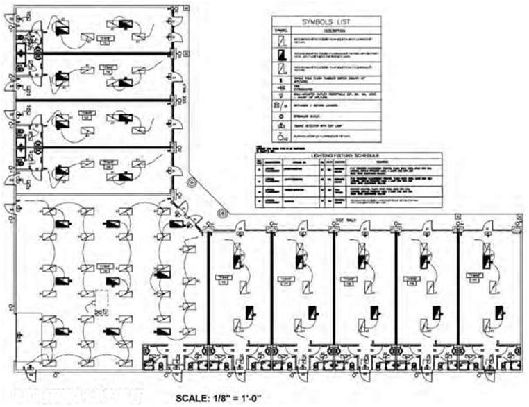
The engineer’s drawing shows the circuiting and switching for each item on the ceiling. The circuit connection to the panel is labeled. Conduit size when required, legends, and general and/ or specific notes are provided on this drawing. The RCP is basically a view of the ceiling from above. It is as if you were floating above the ceiling and looking down at it (Figure 6.22). This view will show the location of light fixtures, drywall or T-bar ceiling patterns, and any items that may be suspended from the ceiling. Figure 6.22 also shows a lighting layout plan.
Many projects will require electrical and mechanical drawings. The interior designer or architect will provide the electrical and/or mechanical engineer with their reflected-ceiling-plan design. The engineer will add the required information.
A reflected ceiling plan is drawn to scale. This means that the plan is measured proportionally to a size that will fit on a drawing sheet. A reflected ceiling plan will most often be at the same scale as the floor plan. A common scale is one-quarter inch = one foot (scale: 1/4 inch = 1 foot, 0 inches). The reflected ceiling plan will be titled with the scale noted at the bottom.
In a reflected ceiling plan each light fixture has an identification letter. A light-fixture legend is included on the actual drawing sheet. In the legend, each fixture is listed with its letter and a specification.
The numbers in the hexagon shape are key notes. They describe items on the reflected ceiling plan. For example: number 2 would list the specification for the T-bar ceiling. Ceiling heights are noted in the oval shape.
The engineer’s drawings must specify the type, location, and number of panels. On large or complex projects a circuit-breaker layout is included. This can take the form of a legend or diagram which typically includes number of panels and ampere loads.
The engineer must provide a load summary of the total connected load (amps/watts) for all items shown on the power and RCP drawings. This ensures that the main service is adequate. Many cities and towns have energy-conservation regulations regarding electrical loads. The engineer’s drawings must abide by all codes and bylaws pertaining to the city, town, or province where the project is located.
The following are typically included in a set of electrical drawings:
• Type and location of outlet, (duplex, dedicated, isolated ground, GFI, etc.)
• Size and type of conduits (data, communication, phone)
• Volts of switches, wiring, and circuitry
• Lamps and model numbers of light fixtures
Other information may be needed, depending on the complexity of the project:
• Direct connections (junction boxes, etc.)
• Emergency lighting and exit signs
• Alarm and security systems
• Fire-alarm systems
• Sound systems, speakers, monitors, and cameras
• Special equipment (kitchen, entertainment)
• Special technical devices (computers, gauges, medical, etc.)
• Special wiring (signs, heating, saws)
Engineer’s drawings are required for all commercial projects involving electrical work, including additions, renovations, and new construction. A permit is required prior to commencing any on-site work.
Drawings and permits are also needed for residential projects when substantial electrical work is to take place. For small projects, a licensed electrician can provide the information required to obtain an electrical permit.
Concept and designs are the first stage of any project. When established, the next stage is construction drawings. Once the floor and reflected ceiling plans are complete, they are passed to the engineer to produce the electrical drawings. The engineer’s drawings become part of the construction-drawing set.
MISCELLANEOUS DRAWINGS
Millwork
Millwork refers to custom, shop-built wood components for interior-finish construction for both residential and commercial work. These are items such as custom wood chair rails, bases, built-in bookcases, paneling, doors, cash units, display fixtures, and so on.
The project interior designer or architect produces the millwork drawings. These drawings provide information about each custom-designed piece. Styles, dimensions, types of wood, finishes, and desired details are drawn and noted.
Millwork items are primarily built of wood, although glass and metal parts may also be included within a fixture. For example, a cabinet for entertainment equipment can have a metal swivel device for the television and a metal rack for DVD storage. A display case may have a wood base with a glass showcase on top.
Wood may include solid wood, wood veneer, MDF, particle board, or plywood. Information on the drawing indicates the specific type of wood—maple, pine, oak, etc.—and whether it is solid or veneer.
The finish is also noted—stained, lacquered, or laminate, for example.
On smaller projects, millwork drawings are typically pages within the construction-drawing set. Onlarger projects it is common practice to create a separate set of drawings. As a separate set the pricing and construction process is simplified. The company working on this portion of the project has all items clearly laid out.
A separate set of drawings also works well for chain stores. The head office will have the custom fixtures designed and drawn. They will then contract out large quantities of standard fixtures directly to a woodworking shop. This enables them to mass-produce items for their stores, such as cash units or display cases. By producing more than one at a time they are able to negotiate a better overall price.
Typically, the general contractor subcontracts the millwork portion of a project to a woodworking company. The contracted company will produce shop drawings when a request is noted on the design drawings. Shop drawings show exact construction methods in detail, including the finish. They are submitted to the interior designer or architect for approval before building starts. This ensures that items are built as intended for the project. Approved shop drawings are then used for building.
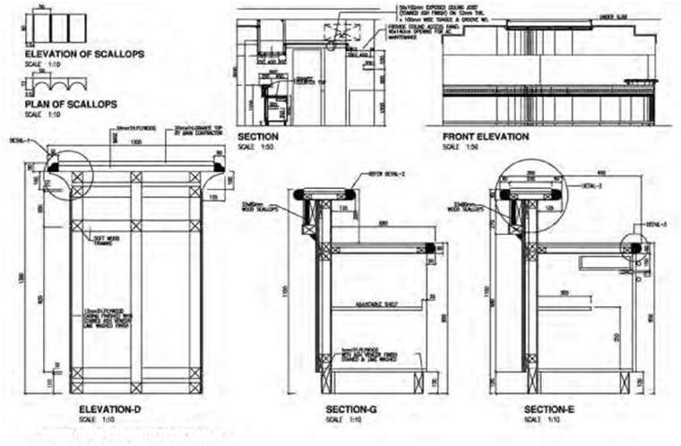
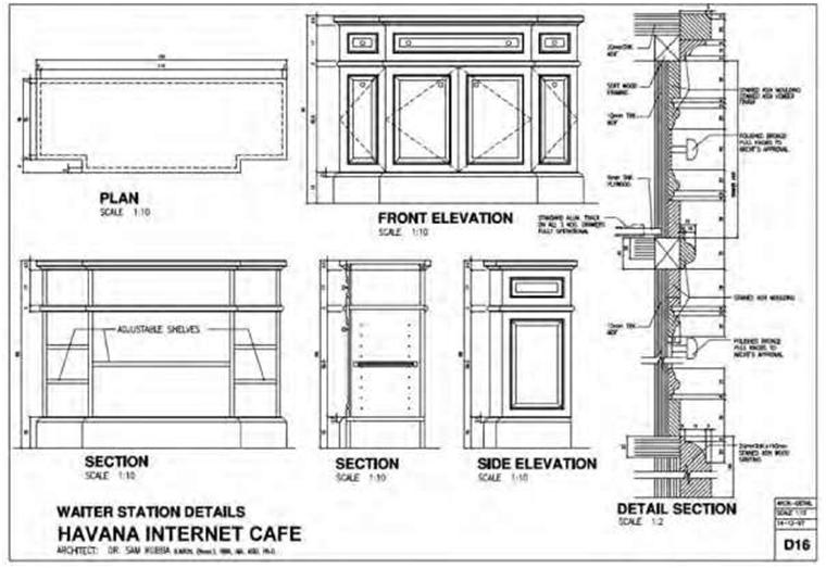
Figures 6.23A,B and C show examples of millwork drawings. The drawings have been reduced to fit on the page and are meant only to provide an overview and not to show specific information.
The drawings will typically show a plan view of the item. Front, side, and rear elevations are used when required to explain the shape. Sections are used when necessary to provide information for various segments. All are dimensioned. Specific materials and finishes are noted.
Shop-fabricated units are preassembled in the shop and shipped to their location in one piece. Fieldinstalled components such as baseboards are shipped in lengths to the job site. They are put in place and fitted on site, using metal fastenings such as screws or blind nailing in combination with the joint.
Details
Architectural details are essentially enlarged drawings of specific construction assemblies and are normally provided by the architect or structural engineer. Their main purpose is to offer greater clarification and understanding where required to implement a project. Contractors frequently request additional construction details during the execution stage. When an area of construction is drawn to a larger scale in
order to clearly show the materials, dimensions, method of building, desired joint or attachment, and so on, these enlargements are referred to as details.
Details are most commonly drawn as sections. It is as if a slice is made through a specific area and the inner components made visible. Detail drawings are one of the most important sources of information available to the contractor about specific parts of the construction. A detail contains both graphic and written information. There are many, many types of details. A drawing sheet will often include several details. The complexity of the project will determine which areas need to be shown at a larger scale. Details are not limited to architectural drawings but can be used in structural and site plans and, to a lesser degree, in mechanical or electrical plans.
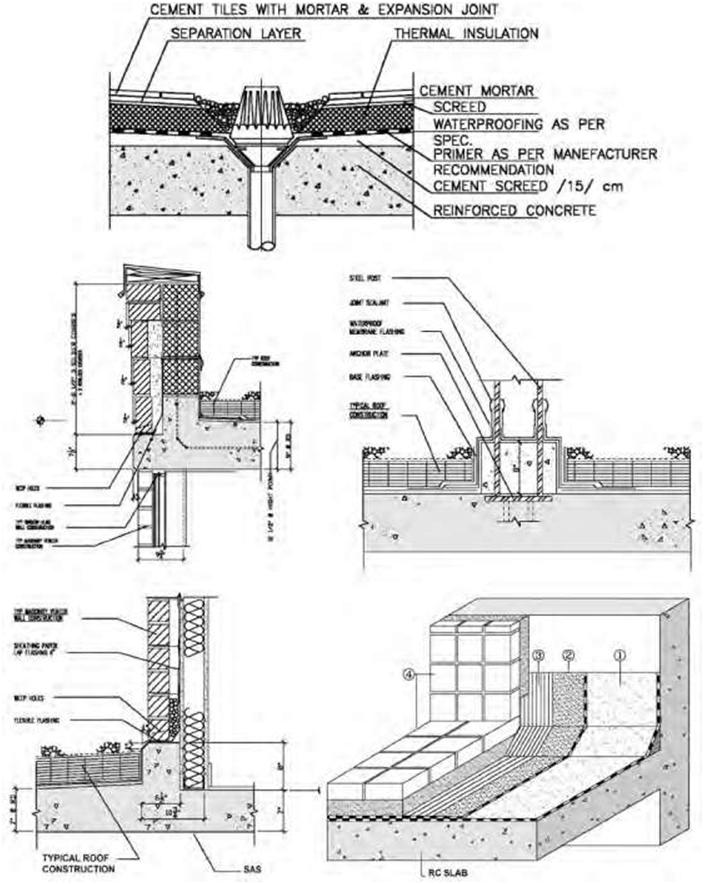
Details are always drawn to scale. A typical scale for a detail is three inches = one foot (scale: 3″ = 1’0″). The scale for each detail will vary depending on how much information is required to make the construction clear to the builder. Each detail will be titled with the scale noted below it. Figure 6.24 shows different types of details found in a typical construction set.
Shop Drawings
Very often the consultant will request shop drawings for certain components during the construction process. These are normally prepared by the contractor, subcontractor, manufacturer, or fabricator, depending on the element being manufactured. Shop drawings are typically required for prefabricated components such as windows, precast components, elevators, structural steel, trusses, or millwork. The drawings represent the manufacturer’s or contractor’s interpretation of the consultant’s drawing and are thus expected to show more specific detail than normally provided by the construction documents. They are drawn to explain the fabrication and/or installation of the required product. The primary emphasis of a shop drawing always relates to the particular product to be manufactured or its installation and excludes information regarding other products unless integration with another product is necessary.
Shop drawings should include information for the consultant to compare to the specifications and contract documents. They should also include dimensions, manufacturing conventions, and special fabrication instructions and should address the appearance, performance, and prescriptive descriptions in the specifications and construction drawings. Shop drawings are designed to assist the consultant in gaining approval of the product and thus should be precise, clear, and as complete as possible. Shop drawings are normally accompanied by samples, catalogs, and any other pertinent information. Any proposed changes should be clearly shown on the shop drawings for the consultant’s approval. Of note, shop drawings are not typically produced by the consultant under the contract with the owner.
I would like to request permission to use drawing 6.22A as an illustration in the 2013 CEE Annual Report. CEE is a nonprofit and will not redistribute, sell, or misuse the image. We will source the image as you require. Please let me know if we can receive a high resolution image and if we can use the image for the purpose described.
Thank you,
Sarah Griffith