

| • Fit work area using two points • Set work plane • Set work plane to view plane • Set work plane by three points • Set work plane to part top • Insert reference model • Copy • Move • Inquire object • Measure horizontal distance • Measure vertical distance • Measure free distance • Measure angle • Measure bolt spacing • Number modified objects • Clash check • Project status visualization • Create a screenshot of a view without borders • Publish as Web page • Show macros • Open model folder • Customize Concrete The Concrete toolbar contains commands for creating concrete parts and reinforcements. |
|||
 |
|||
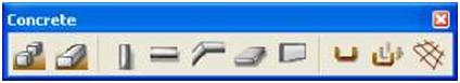
| • Create pad footing • Create strip footing • Create concrete column • Create concrete beam • Create concrete polybeam • Create concrete slab • Create concrete panel • Create reinforcing bar • Create reinforcing bar group |
|||
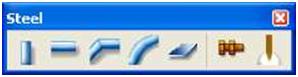
| • Create reinforcement mesh Steel The Steel toolbar contains commands for creating steel beams, columns, and plates. | ||
 |
||
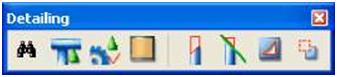
| • Create column • Create beam • Create polybeam • Create curved beam • Create contour plate • Create bolts • Create weld Detailing The Detailing toolbar contains commands for trimming parts. |
||
 |
||
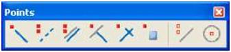
| • Open component catalog • Create current connection • Display the AutoConnection setup dialog box • Create face surface treatment • Create fitting • Create line cut • Create polygon cut • Create part cut Points The Points toolbar contains commands for creating points, construction planes, distance variables, and construction objects you can use to place structural objects in a model. |
||
 |
||
| • Add point along extension of two picked points • Add points on line • Add points parallel to two picked points • Add projected points on line • Add points at intersection of two lines • Add points at any position • Add construction line |
||
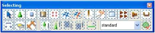
| • Add construction circle using center point and radius Selecting The Selecting toolbar contains commands for selecting objects. | ||
 |
||
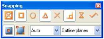
| • Select all • Select connections • Select parts • Select surface treatments • Select points • Select grid • Select grid line • Select welds • Select cuts and fittings • Select views • Select bolts • Select single bolts • Select reinforcing bars • Select loads • Select planes • Select distances • Select component • Select objects in components • Select assemblies • Select objects in assemblies • Select tasks • Available select filters • Select filter Snapping The Snapping toolbar contains commands for picking different positions and points. |
||
 |
||
| • Snap to points and grid intersections | ||
| • Snap to end points • Snap to center points • Snap to mid points • Snap to intersection points • Snap to perpendicular points • Snap to nearest points • Snap to any position • Snap to reference lines/points • Snap to geometry lines/points • Auto • Outline planes |