Tekla Structures – Settings

Units and decimals
To configure how units and decimals are input, output, stored and displayed, click Tools >Options > Options… > Units and decimals.

Update                        When you click OK in the Units and decimals dialog box, Tekla Structures updates the format

of units and decimals in all open dialog boxes.

Input and output Different types of data are separated onto three tabs in the Units and decimals dialog box. Inputdata                             data appears on the Modeling and Catalogs tabs. Output data appears on the Analysis results

tab (output data only relates to structural analysis).


Modeling func-           The settings on the Modeling tab affect the data you use when using modeling commands, such
tions                            as copy, move, create grid, create point, part location, and dimensions.
Catalogs                     Settings on the Catalogs tab affect the data stored in the profile and material catalogs.

No effect                     Settings in the Units and Decimals dialog box have no effect on drawings, reports, or the

Inquire and Measure tools.

The number of decimals affects input and storage accuracy. Always use a sufficient number of decimals.
Exponent notation The decimal point symbol is always a period (.). It cannot be changed. You can use positive exponent notation, but not negative exponent notation.
Imperial units
You can input length in imperial units in the following ways:

•      Inches in decimals (e.g. 300.5″)

•      Feet in decimals (e.g. 62.7′)

•      Fractional notation (e.g. 60′-6″)

In fractional notation, all input is shown in feet (‘) and inches (“). If you are using imperial units and want to use fractions, you must use fractional notation.

Fractional notation
162 TEKLA STRUCTURES 14.0 Settings and Tools
Mouse and pointer settings
You can configure your mouse and pointer settings to suit the way you work using:
•     Pan 

•     Drag and drop 

•     Xmouse 

•     Xsnap 

•     Rollover highlight 

Pan

Pan toggles the function of the middle mouse button between panning and scrolling. Toswitch between scrolling and panning, click Tools > Options > Middle Button Pan, or pressShift+M. Scrolling moves the “viewer”, and panning moves the model. Hold down the middle button and drag the pointer away from the origin of the object. To scroll faster, drag the pointer farther from the origin mark; drag closer to slow down. You can use Scroll and Panwhen other commands are active.

Drag and drop

With Drag and drop active, you can use drag and drop to move or copy parts. You can also modify polygon shape using drag and drop. You cannot drag and drop components, component parts, bolts, or welds.

Activate                      To toggle Drag and drop on and off, use the keystroke D, or Tools > Options > Drag and Drop.

It remains active until you switch it off.

Tekla Structures remembers this setting between sessions by user name.

To avoid accidentally dragging and dropping parts, de-activate drag and drop when you are not using it.
Smart Select               With both Drag and Drop and Smart Select active, you can drag and drop handles without
selecting them first.
To toggle SmartSelect on and off, use the keystroke S, or select Tools> Options > Smart Select. It remains active until you switch it off.

Tekla Structures remembers this setting by session and user name.

Xmouse

With Xmouse active, moving the pointer over a view activates the view. Without Xmouseyou have to click on a view to activate it. To toggle Xmouse on or off, click Tools > Options >Xmouse. A checkmark appears next to the menu option if Xmouse is already active.

Using Xmouse           Xmouse is useful when you are using two views that partly overlap. See the following examples:

•     If you want to pick beam positions from two overlapping views, with Xmouse active you simply move the pointer over the view to activate it.

      With Xmouse active, you can also use the Page Up, Page Down and arrow keys in overlapping views, without having to click a view to activate it first..

TEKLA STRUCTURES 14.0 163Settings and Tools
Xsnap
Xsnap helps you to snap to the correct points by giving you visual cues. As you move thepointer over an object, Tekla Structures automatically highlights the points it suggests you snap to.
Activate                      To toggle Xsnap on and off, use the keystroke T or Tools > Options > Xsnap. It will stay active

until you turn it off.

Tekla Structures remembers this setting by session and user name.

Snap            Use snap switches to control the kind of items to which the cursor reacts

Rollover highlight

As you move the mouse pointer over objects in rendered model views, Tekla Structures highlights the objects in yellow, so that you can easily see which objects you can select.

Activate                      To turn Rollover highlight on and off, press H or click Tools > Options > Rollover highlight.
Phases

In Tekla Structures, you can use phases to break up a model into different sections. Phases are often used to indicate erection sequences. You can create reports and views, hide objects, and copy objects from other models, according to their phase number.

Example                      For example, you have a large  on which several users will work simultaneously in single-

user mode. First create a basic model which includes, for example, the columns. This is phase 1. You then copy this basic model to all users.

Each user then works on a separate part of the building. As each part of the model is completed, you can copy it back to the basic model as a separate phase (phase 2, 3, etc.).

Working with              To work with phases, click Tools > Phase Manager…The Phase manager dialog box appears.

phases

164 TEKLA STRUCTURES 14.0 Settings and Tools
The following table explains how to use the buttons in the Phases dialog box.
Button Description
Filter Lists the phases by the number and/or name criteria you enter..
Set current Makes the selected phase the current phase. Tekla Structures assigns all objects you create after setting a phase to current to the current phase. The @ character in front of the phase number indicates the current phase.

Select by objects

Highlights the phases associated with the objects currently selected in the model. Use this button to identify the phase of an object.
Add Creates a new phase.
Delete Deletes the phases you select from the list.
Select by phase Selects and highlights the corresponding objects in the model if you have selected associated phases on the list.
Modify phase Changes the phases of the selected objects to the phase selected on the list.
Additional properties You can add more phase properties, which will appear as extra columns on the list. Tekla Structures considers phase properties to be user-defined attributes, so you can define the names of phase properties in the objects.inp file. See Adding properties. To use phase properties in reports and templates, use the syntax PHASE.ATTRIBUTE_NAME in the phaseproperty field name.
TEKLA STRUCTURES 14.0 165Settings and Tools
Options
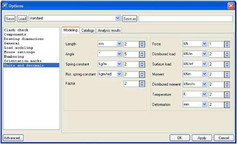
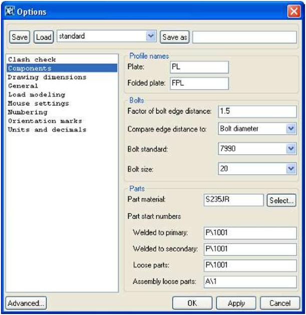
Use the Components dialog box to set various default values for numbering, coefficients, profile names and connections. To open the Components dialog box, click Tools > Options >Options… > Components.
See also To save your settings, click Apply or OK.
Preferences in the online help
Orientation marking settings in the online help
You can specify the color of some model objects by defining their class with a number.
You can also use the object representation settings to specify colors for defined object groups. You have the following color options:
166 TEKLA STRUCTURES 14.0 Settings and Tools
Color Number
black
light gray or white 1
red 2 or 0
bright green 3
blue 4
cyan 5
yellow magenta
gray 8
pink 9
lime 10
aqua 11
lilac 12
orange 13
light blue 14
You may also need to use the numbers of colors with some variables, for exampleXS_CLASH_CHECK_COLOR. For more information, see the online help.
General settings
Tekla Structures also includes the following general settings:
Snap grid
Use Snap grid when picking a point using the Snap to any position snap switch.  To define a snap grid, click Tools > Options > Options… > Mousesettings.

Enter the following information:

Field Description
Activate snap grid when free snap is on Check to make the snap grid active.
Spacing x, y Snap grid spacing
Origin dx, dy Offsets for grid origin
TEKLA STRUCTURES 14.0 167Settings and Tools
Beep
With this switch active, Tekla Structures warns you with a beep when an error occurs. ClickTools > Options > Beep to toggle this switch on and off.

Leave a Comment

This site uses Akismet to reduce spam. Learn how your comment data is processed.