
| Introduction There are two ways to create bolts: • Create a single bolt group • Apply a component that automatically creates bolt groups. This section concentrates on creating single bolt groups. For more information on using components to automatically create bolt groups, see Defining bolts and welds in the Detailing Manual. You can create different part marks for holes and bolts in drawings. You cannot use bolt elements (such as screws, washers, and nuts) while you are creating holes, as Tekla Structures uses the same command to create bolts and holes. Creating You can use bolts to create and connect assemblies. You can create nested assemblies by assemblies connecting sub-assemblies to an existing assembly, or you can just connect more parts to assemblies using bolts. Use the Connect part/assembly and Bolt type list boxes in the Bolt properties dialog box to control how Tekla Structures creates assemblies. The order in which you select parts when |
|||
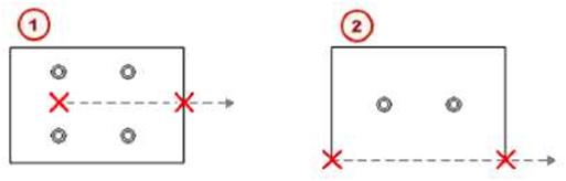
| Array | |||
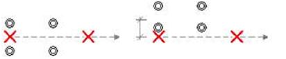
| © © | • Bold dist X: 150 • Bold dist Y: 100 xy list • Bold dist X: 75 175 |
||
| • Bold dist Y: 100 100 You can also create a new bolt group by modifying an existing one. In most cases it is easier to create bolt groups by applying a component including bolt groups, using the following method: 1. Apply a component. 2. Explode the component. 3. Modify the bolt group. You can change which parts a bolt group connects using the command Detailing > Bolts > Edit Bolted Parts. This command prompts you to reselect the main and secondary parts. Tekla Structures automatically updates bolt length to suit these changes. For more information, see Bolt length calculation in the online help. Tekla Structures creates holes in the same way as bolts, but you do need to change some of the properties in the Bolt properties dialog box. You can create the following types of holes: • Round • Oversized • Slotted • Tapped To create a round hole, follow the steps in Tekla Structures calculates the diameter of a round hole as the sum of: • Bolt size • Tolerance (hole) To only create a hole, clear all bolt element checkboxes in the Bolt properties dialog box, as shown below: |
|||
 |
||||
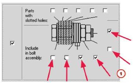
| © | Clean these checkboxes to create a mere hole | |||
| Creating slotted holes You also use the Bolt properties dialog box to create slotted holes. 1. Select the checkboxes against Parts with slotted holes to indicate which parts should be slotted. |
||||
 |
Tekla Structures counts the pieces of steel from the head of the bolt down. For example, if you select the second checkbox from the head of the bolt, Tekla Structures slots the second piece of steel from the head of the bolt. |
|||
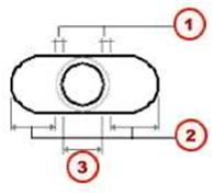
| 2. To only create a slotted hole, clear all the Include in bolt assembly checkboxes. 3. Select Slotted in the Hole type list box. 4. Enter the allowance for the slotted hole in the x and y directions of the bolt group using the Slotted hole X or Slotted hole Y fields. |
||||
 |
||||
| fl) Tolerance f2J Slotted hole X or Y f3J Bolt size |
||||
| 108 TEKLA STRUCTURES 14.0 Detailing | ||||
 |
You indicate the x direction of the bolt group when you create the bolt group | ||||||||||||||||||||||||||||||||||
|
5. If the bolt connects several parts, you may want to rotate alternate holes by 90 degrees. This allows the bolt to move in different directions. To do this, select Even or Odd in the Rotate slots list box. |
|||||||||||||||||||||||||||||||||||
 |
|||||||||||||||||||||||||||||||||||
| MJ Crossing slotted holes to odd or even parts (2J Parallel slotted holes | |||||||||||||||||||||||||||||||||||
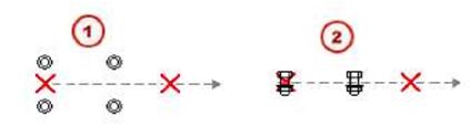
| Creating oversized holes Use the Bolt properties dialog box to create oversized holes. 1. Select the checkboxes against Parts with slotted holes to indicate which plies of connection get oversized holes. 2. To only create a hole, clear all the Include in bolt assembly checkboxes. 3. Select Oversized in the Hole type list box. 4. Enter the allowance for the oversized hole in the Oversize field. You can also use a negative value to create smaller (tapped) holes. You have the following options for bolt group shape: • Array for rectangular • xy list for any shape • Circle for circular Tekla Structures uses the values in Bolt dist X and Bolt dist Y to determine how many bolts the bolt group contains, as shown in the table below: |
|||||||||||||||||||||||||||||||||||
|
|||||||||||||||||||||||||||||||||||
| Single bolt | To create a single bolt, set Bolt group Shape to Array and enter “0” for both bolt distances. | ||||||||||||||||||||||||||||||||||
| TEKLA STRUCTURES 14.0 Detailing | 109 | ||||||||||||||||||||||||||||||||||
| Bolt properties The bolt properties are: | |||||||||||||||||||||||||||
|
|||||||||||||||||||||||||||
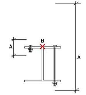
| Bolt length Tekla Structures calculates bolt length automatically, using the material thicknesses of the connected parts, and other factors. The following settings in the Bolt group properties dialog box affect bolt length calculation: • Thread in material • Cut length • Extra length Thread in material indicates if the thread of the bolt can extend beyond the bolted parts. Tekla Structures does not use this value when calculating the length of full-threaded bolts. Cut length indicates the area Tekla Structures should search for parts that belong to the bolt group. Using cut length you can determine whether the bolt will go through one flange or two. In the illustration below, A is the cut length and B is the bolt origin. Tekla Structures calculates the search area as A/2 in both directions from point B. |
|||||||||||||||||||||||||||
 |
|||||||||||||||||||||||||||
| Tekla Structures warns you if the cut length is too small (i.e. the bolt group contains no parts) and makes the bolt length 100 mm. | |||||||||||||||||||||||||||
| PHI | If you want to force a bolt to be a certain length, enter a negative value for length (e.g. -150). | ||||||||||||||||||||||||||
| Using Extra length to increase the material thickness Tekla Structures uses when calculating bolt length. For example, you might need extra bolt length to allow for painting. You can also build additional lengths into bolt assemblies . | ||||||||
| T |
If there are large gaps between connected parts, the gap is added to the length of the bolt. Tekla Structures calculates bolt length using the the total distance between the first and last surfaces. |
|||||||
| See also | Bolt catalog Bolt length calculation |
|||||||
| Bolt group location | ||||||||
| Tekla Structures determines the location of the bolt group using the following values: • Bolt group x axis • Work plane The two points you pick to create the bolt group determine the bolt group point of origin and its x direction. Position on plane Position on plane moves the bolt group perpendicular to the bolt group x axis. |
||||||||
 |
||||||||
| Position at depth Rotation | Position at depth moves the bolt group perpendicular to the current work plane. Rotation defines how far the bolt group is rotated around the x axis, relative to the current work plane. For example, you can use this field to indicate on which side of the connected parts you want the bolt head to be. |
|||||||
 |
||||||||
| Front | ||||||||
| © (2j Top |
||||||||
| Offsets | You can also use offsets to change the position of the bolt group. Offsets move the bolt group by moving the x axis of the bolt group. The starting point values Dx, Dy and Dz move the first end of the bolt group, relative to the bolt group x axis. The end point values move the second end of the bolt group. • A positive Dx value moves the starting point towards the end point. • Dy moves the end point perpendicular to the bolt group x axis on the current work plane. |
|||||||
| • Dz moves the end point perpendicular to the current work plane. | |||
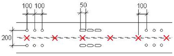
| Example An example showing the parameters of a bolt group. | |||
 |
|||
| Bolts created using the bolt properties: | |||
| • Bolt group Shape = Array, Bolt dist X = 100 100, Bolt dist Y = 200 • Slotted hole X = 28, Bolt size = 20, Tolerance = 2 (overall dimension = 50) • Starting point, Dx = 100.0 |
|||