
I would assume that almost all the readers of this text have already heard of the acronym CAD (computer-aided drafting). However, I will not assume that everyone has worked with it. CAD is the graphical process of drafting a part or an intended area, with vectors, in which CAM operators will be applied. It is most often used as the starting point in the “concept-to-part” process. CAD is extensively utilized in manufacturing industries throughout the world. Once the user is even somewhat proficient with a CAD package, a graphical representation of a part may be drawn (typically to a 1:1 scale) in a fraction of the time it would take to draw with pencil and paper. CAD also allows you to easily edit and make changes to the file without having to produce an entirely new drawing.
CAD is quite simple to use and most software packages have built-in help facilities as a guide. In addition, there are often numerous texts and eBooks available that are specific to your brand of CAD, as well as courses available from the manufacturer or from your local college. As most CAD packages are capable of performing so many more functions than what you will be typically needing to draw your part, I would recommend you first “play” with your CAD package to familiarize yourself with the basics. Topics such as rendering and hatching, etc., are not required elements for CNC operations. If you are still uncomfortable, see if your CAD manufacturer has any additional free learning material that is available on their Web site or that they might mail to you. I usually find additional tutorial material to be very valuable as they contain many examples where they “walk” you through using most of the commands. Please bear in mind, that if 2D (i.e., two-dimensional) drawings will be your sole or even primary use of CAD, you will not need the latest and greatest nor most expensive version available. In fact, even the most basic of a CAD drawing package will provide sufficient features for the CNC user to accomplish any task.
What are some of the things that CAD can do? Consider the computer’s screen background to be a canvas or grid that represents the first quadrant of a Cartesian coordinate system. This drawing grid typically is sized to either represent the piece of raw material you are milling your part from, or it represents the overall size of your machine’s cutting area. Via pull-down menus or screen icons, the user has the ability to select any type of basic geometric shape and “draw” it anywhere on the grid. With CAD you do not have to scale down your drawings as is often done with the paper and pencil approach, which is typical to get all of the drawing all on one piece of paper. Hence, your drawing can be on a 1:1 scale and you can zoom in and/or out to view any portion of the drawing. You have drawing tool selections that will include a line segment, parallel lines, circles, arcs, ellipses, rectangles, line offsets, etc. You may also join segments together via “snap” commands so that there are no gaps or overlays in the part you are drafting – this is something that is very important as you will see in the CAM section of this chapter. Snaps allow the user to snap to the start and/or ending points of an existing arc or line segment, or an established grid point on the drawing canvas. All vectors have both starting and ending points and are referred to as nodes. It is critical in CNC machining that your line segments are all joined together, node to node.

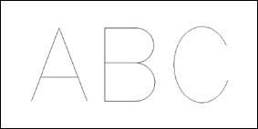
Beyond the ability to draw your image from scratch, CAD programs allow the user to import other vector drawings, as well as apply text. The two types of text (font independent) will either be engraving or stick font text and TrueType text and are both are comprised of vector line segments. Examples of both types of text are shown in Figs. 8-1 and 8-2.
Pay particular attention to the difference between these two types of font types. In the TrueType example, each vector segment is bounded, meaning there are no open vector segments. Stick fonts, on the other hand, can have both open or closed boundaries. You will notice this type of font used in engravings where the text is less than 1 in high and usually cut with conical engraving bits.
Before going any further, I would like to ensure that each reader understand why a paint type of program will not work in lieu of a CAD package. Drawing programs (such as Microsoft Paint) represent objects on the computer screen by illuminating pixels that are (loosely termed) “painted” onto the screen – one small square at a time. All images such as .jpg, .gif, and tif are all considered raster format and use pixelation to represent the object. If you use a paint program and zoom in, you will see jagged edges between the transitions between one pixel to the next. (An example can be seen in Fig. 8-3, where we zoom in on the center portion of a letter X.)
Vector files work on a completely different principle. Each and every vector consists of a discrete line segment and is represented by a starting and ending point, with a line connecting the two. These points can either be very close together or a large distance apart. Note that typical 2D vector files are easily also recognized by their file extension type: .dxf, .dwg, .ai, .eps being the most common.
Raster to Vector Conversion Utilities
Some CAD programs, as well as stand-alone software utilities, allow the user to import raster type images for conversion to a vectorized image. These are commonly referred to as raster to vector utility programs and there are many to choose from. This type of program traces the raster picture with vector lines and typically has threshold parameters to control the amount of smoothness the resulting trace will have. The author has used CorelTrace, which is by far the most powerful and easiest to use trace utility. It is available either as a stand-alone program or comes packaged with CorelDRAW. It allows object traces that are either inside, outside, or along the center line of the raster image.
If you are the type of user needing to convert photographs or any pixilated graphics, this type of tool will be very useful. A Web search will yield many such utilities that range from free to several hundreds of dollars. If you are interested in the freeware or shareware versions, they may be obtained from http://www.shareware.com/.
Difference between 2D and 3D
Both in this book and from other users, you will hear the term two-dimensional (2D) or 2½ D (another equivalent term) cutting versus three-dimensional (3D) cutting. There is a very basic distinction between the two.
• In 2D cutting, the cutter is moved to its intended cutting depth and held stationary while X, Y or both X and Y movement takes place. All CAM software is capable of performing 2D milling cuts. A classic example of this is where an item is profiled milled out of a section of flat stock.
• In 3D cutting, the cutter is allowed to move up and down while the X, Y or both the X and Y traverse through the material. This type of motion produces rounded contours in the material, without the need for round over or cove-style tooling. You will often see this type of milling used in sign work or dimensional facial artwork, etc.
Listing of CAD Vendors
Listed below are several of the most widely used CAD and graphics applications that are currently available. There are a wide range of not only cost, but types of features within those that are mentioned. It is of great importance for the novice to understand that an expensive program or one with more bells and whistles are not necessarily needed nor even desired! In fact, you will quickly realize that creating or editing a vector image only requires the most basic set of tools that any CAD graphics package has to offer.
AutoCAD and AutoCAD-LT
Without a doubt, AutoCAD is the world’s leading PC-based CAD manufacturer. They have been around for a long time and you will find that other CAD programs will compare their software relative to AutoCAD as it is considered the standard. It is both “command line”-based as well as icon graphical, meaning that the user enters the various commands via the keyboard, or is able to just use the mouse. It seems to give the user the best of both worlds. I have used AutoCAD for many years in the past and have to admit that it is a very full featured program. It is capable of handling any 2D or 3D drawing task you may have. There are also more direct and aftermarket texts and tutorials available for this product than any others I have seen. They also have a 2D-only version of their product called AutoCAD-LT (light). Generally all you will need in most CNC work will be 2DCAD. The people at AutoDesk have also recently added a version that will work in a Macintosh operating system environment.
One drawback to using a command-line approach is that if you do not use it often enough to remember what the commands are, it takes the user a while to get back into the swing of things. Of course, you always have the “point and click”-icon driven method available – which is what most all other CAD manufacturers use by default. Another drawback for many users is the cost of these programs.
Currently, the initial cost for AutoCAD is $3,995.00 with upgrades from previous versions running from $595.00 to $1,795.00. The initial cost for AutoCAD-LT is $1,200. To view their package information and up-to-date pricing visit: http://www.autodesk.com
TurboCAD
TurboCAD is also a very popular choice among CAD users. It is a fully icon graphics-driven package that most find the easiest of all to use, and is considered to be the main contender to the suite of AutoCAD products. Most find that TurboCAD is easier for the novice to learn and operate, but it is often the difference in price that determines which of the two a user will purchase. In contrast, TurboCAD’s high-end platinum version retails for $1,500. There are also versions available for those who use Apple Macintosh for their graphic workstation. My particular use of this program, however, is not intended as an endorsement for readers of this book as I make use of this software in areas outside of CNC. Several years ago, the author purchased a used copy of TurboCAD from a bookstore for a considerably reduced price. I also purchased a very reasonable upgrade version. Most users of CAD for CNC purposes only utilize a small percentage of the package’s overall ability, hence, even older versions of CAD are just as useful as an up-to-date version. The reader can see all of the IMSI products by visiting their Web page: http://www.turbocad.com
Free and Low-Cost CAD
There are many programmers around the world who have written their own CAD software package, and is available either as free or at very little cost. The main search engine to find this type of freeware or shareware is: http://www.shareware.com. There you will find literally dozens of CAD programs which can be downloaded. In addition you will find numerous other programs, such as CAM, raster-to-vector conversion tools, graphics utilities, etc., that can suit many of your needs.
QCAD
One program that can be found at http://www.ribbonsoft.com/ $31 USD for Windows or Macintosh versions and free for Linux users is QCAD, which is a powerful 2D CAD package that is more than capable of handling pretty much any drawing task required of most beginning and intermediate CNC users. QCAD is my favorite program to use while working in a Linux environment.
Graphics Programs
Apart from the paint style of programs are several graphics software programs that have the ability to either work with or save the resulting output in a vectorized format. These programs are not marketed as CAD as their overall approach and use to drawing is more of a free-form style. Depending upon the type of application or, more specifically, your style of application will determine if a graphics style of program is better suited than a CAD package.
If your work is primarily within the signage industry, the use of a graphics program will allow you to produce a graphical layout (with color) to present to the customer. From this artwork, the desired vectors are easily extrapolated and saved for use with CAM software. There are many graphics programs available; however, not all of them have vector ability. For any not listed here, it is the reader’s responsibility to determine prior to purchase if the program, indeed, has this ability and that the CAM program can import the output file prior to purchasing it.
Listing of Common Graphics Programs
Adobe Illustrator – http://www.adobe.com/products/illustrator/ – very popular program for free-form artwork and extensively used in the signage industry. Very expensive.
• Rhino – http://www.rhino3d.com/ – used in several industries, such as, free-form artistry, metal machining, and mold production. Has optional CAM program. Very expensive.
• GIMP – http://www.gimp.org/ – excellent graphics program. Versions available that run in both MS Windows and Linux operating systems. The cost is free.
• SolidWorks – http://www.solidworks.com/ – has become an industry standard for use in rapid prototyping, mold making, etc. Very expensive.