
The decision to use CAM or not is largely dependent upon both the time and geometry of the item to be manufactured. Often, users either already have a CAD drawing or can rather quickly produce one to obtain any required dimensions in which to reproduce the item. The use of CAM affords the user to quickly yield a resulting tool path that, based on certain user-input criteria, can be used in the physical process. The required user inputs will include, but are not limited to, tooling used, depth per pass, plunge, and safe retraction of the Z-axis for moves in between cuts, feed rates for both cuts, and rapid moves, etc., all within the Cartesian coordinate system. Furthermore, all of the aforementioned parameters are output in an order of operations such that interior cutting functions are executed prior to peripheral operations, allowing the part being machined to remain affixed in place.
The user may also manually produce the G code – in essence by bypassing the use of a CAM tool. In this instance, it is the programmer’s responsibility to individually denote the order of operations that would resemble those required to machine the same item if produced using a CAM software tool. The process sounds straightforward; however, for large files the task can be rather daunting. In addition, the G-code commands can either be saved into an ASCII text format for automated controller execution, or the same commands can be manually issued one at a time directly within the controller software via the man data interface (MDI). When this approach is taken, it is generally referred to as block processing.
There are yet other times when it can be advantageous to make use of both CAM and manual programming techniques. For instance, if the same item to be manufactured needs replication within a large sheet of material, the programmer can often save the CAM output in a separate file naming the file as a subroutine, thus denoting where on the sheet of material to repeat the same cutting operation. What this achieves is to greatly reduce the overall size of the cutting file by only providing the cutting parameters one time rather than multiple times in multiple locations. Please note that detailed examples demonstrating the use and operation of a main file calling a subroutine are covered in Chapter 11.
Understanding and Using CAM
Overall, the decision to use a CAM software tool or not depends upon the type of industry you are involved in. For instance, if you are producing 2D artwork for the signage industry, the use of CAM is almost a given. What would take an experienced G-code programmer hours (if not days) to produce an output file of a string of TrueType font letters nested on a sheet of material would only take minutes with a CAM program. Conversely if you are mainly doing 2D single-part file programming for mass production, it can be advantageous to manually write the necessary G-code commands to help streamline the cutting operation to yield the greatest number of widgets per hour of production.
It ends up being the users’ responsibility to decide if they would benefit from using CAM versus a manual approach and also to decide when and where a combination of both would be worth the effort. To assist users in the manual only or combination approach, there are numerous G-code editing tool packages available to help the user in the manipulation of the code itself.
CAM, more so than CAD, is considered to be an intelligent piece of software. It accepts a vector-based graphical input file from which to work. The user then supplies the needed information, thus allowing the software to produce an output file with the properly ordered and formatted movement commands. CAM is an acronym standing for computer-aided manufacturing and is a software tool that establishes the cutting tool paths, feed rates, and outputs that result in a G-code format.
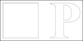
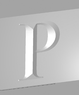
Each of the various methods available for use produce a G-code cut file that can have advantages associated with them – often based upon the size or quantity of the part(s), but, most importantly, the ease of obtaining the shape or geometry of the item you wish to manufacture. Bear in mind that absolutely anything can be manually programmed in G code, but not everything you may want to produce can be quickly and easily achieved by standard geometric shapes (i.e., circle, square, rectangle, hexagon) that manual programming can account for. To illustrate the comparison of the level of effort required between manual programming and automated CAM, consider a simple example, such as a simple square versus (for example) the letter “P” in a Times New Roman TrueType font (see Fig. 9-1). Visually, the reader can realize the differences in complexities between the two. From a high-level perspective, the square will have four straight sides to work from. The letter P, on the other hand, has both an interior and exterior vector path to traverse, along with transition curves or radii joining each of the horizontal and vertical connecting lines. Clearly, it is at these times that having a CAM program can make your life much easier when compared to manually attempting to input the necessary G-code commands.
For those who are not already familiar with what this software does for you, we will be going into some detail as to its purpose and examples of use. What the user inputs to CAM determines when and where the cutter bit is to enter the material, traverse along the vector path, the direction of the path, and retraction for subsequent moves, along a safe path and height above the material. CAM automates these tasks (and more) with relatively minimal user input.
Overall, CAM provides the user the following:
• Reorder of vector line segments
• Check for open vector paths
• Establish tool paths
• Z-axis up/down for rapid traversing
• Start/stop and adjustment parameters for the application
• Provide G-code output file.
This summary of operations is discussed below in more detail.
The order of the line segments when drawn in CAD is something that is saved within the CAD file format. For example, if a box is desired and you initially only draw three of the four sides, then draw or edit somewhere else within the drawing and, finally, come back to draw the fourth side – all of these order of operations are recorded in CAD. Thus, CAM will reorder these vector line segments to make them contiguous or linked together. CAM also checks the drawing to see if there are any open vector paths and will typically denote any breaks with some type of a marker for user intervention. This allows the user to link together any unintended breaks in the artwork. Note that these types of errors can usually be avoided via the use of snaps while producing the artwork in CAD. Once the user has input the needed required data, CAM will produce what is referred to as a tool path. The location of the resulting paths are directly dependent upon the type of tooling the user has selected. For an application, such as routing or milling, the paths will be one-half the diameter of the chosen tool and typically located within or outside of the vector boundary. When producing a part that has both an inner and outer boundary or for multiple parts, the CAM program will establish plunge and retraction moves for the Z-axis, both for cutting and noncutting types of moves. This is required, as to not have the tool buried in the material when moving from location to location. Finally, almost all CAM programs accept user input that will be specific to the application. If using a high-frequency spindle head, for example, the user can select within CAM the tool number and the rpm to operate at. Thus, in the resulting output of the G-code file, there will be instructions to enable the spindle at the proper frequency and issue another command at the end of the file to turn off the spindle.
CAM Machining Parameters
In this section, we detail the common types of machining parameters found in CAM tooling setups. Please note that the terms describing the parameters that are listed here may or may not coincide with the same terminology used in your particular CAM package, but they will be close and perform giving the same end result.
Profiling – Inside and Outside
Profiling is the most basic type of milling or cutting operation. As the name implies, the resulting tooling path will profile (i.e., interior or exterior side) the vector boundary. Note that for this example we will restrict our discussion to use one router bit (¼-in diameter or ⅛-in radius) for all cutting operations. In the event that more than one tool is used, it is referred to as rest machining.
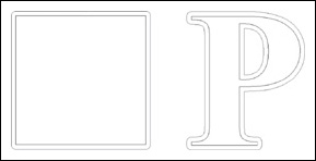
Figure 9-2 shows an example of a capital letter P in a Times New Roman font 4 in in overall height. The material to be used is ¼-in thick and is being cut from a large piece of sheet stock.
First, the reader should note that there will be two perimeter or profile cuts required to complete this operation. This is a very important aspect to the “order-of-operations” approach in CNC milling. As the part is being produced from sheet stock, the interior portion of the letter must be milled out prior to the outer portion. Consider if the outer profile of the letter were cut first, it would be much more difficult to retain the remaining material in its proper place on the spoil board to allow the interior profile operation to complete. Most, if not all, CAM programs have the built-in intelligence to identify if a vector boundary does or does not have an interior boundary located or nested inside of the other. Once the ¼-in thick material (for example, Fig. 9-2) is placed on the spoil board and the cutter bit zeroed to the top of the material, the user would observe the following generic order of operations for this example:
- the bit will move to the start/stop point for the interior profile of the part
- the bit will move down into the material and stop at a ¼-in depth
- the bit will traverse along its cut path until it reaches the same start/stop point
- the bit will retract up to its determined “safe Z” height
- the bit will move to the outer perimeter start/stop point
- the bit will move down into the material and stop at a ¼-in depth
- the bit will traverse along its cut path until it reaches the same start/stop point
- the bit will retract up to its determined “safe Z” height
- the bit will return back to its X = 0 Y = 0 location
An important note is that this same overall order of operations will be generically the same for almost all CNC operations. Note these operations are very repeatable and predictable. Obviously the same operations would apply to the square shown in Fig. 9-2.
Area Clearance
This operation does just as its name implies. It clears out or removes material from a selected area that is bounded by a closed vector path. This function can be used to accomplish a host of differing results. Among these are pocketing a hole or pocketing an area that does not extend through the material. The area can be square, circular, or rectangular, flattening a work piece to a desired thickness, or removing only certain material while leaving other areas untouched, such as in milling a boss. A common example is when raised lettering is desired to be left on some material. The area clearance operation would be performed to all of the material where there is no lettering. Obviously you would not want to remove the full thickness of the sheet material as this would leave individual cut out letters. In essence, the lettering is left untouched and ends up raised, as compared to the surrounding areas.
The types of moves that are made to remove the material is usually user defined. There are two basic types of removal schema: raster or circular (Fig. 9-3). In raster, the cutter bit moves in one direction as far as possible and then advances a user-defined overlap distance and resumes cutting back along a parallel path to the previous one. Circular removal works basically the same, but with removal paths based upon the vector boundary shapes.
Cut Along a Line
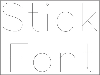
This is a function that is often used in producing decorative types of cuts. Any type of router bit can be used – straight tipped or pointed. Often a ball-nose type of cutter bit is used to produce decorative fluting in millwork. Round-over bits used with this type of operation produce nice round-over profiles on stock as well. One of the most widely used times this operation is employed is during text engraving. The type of font that is used when the “cut along a line” option is enabled is referred to as a stick font (Fig. 9-4). Stick fonts differ from TrueType fonts in that they do not make use of closed vector boundaries. They are comprised of lines and arc segments that represent the shape of the letter.
Drilling Function
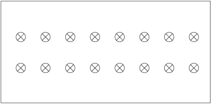
Your project will often require circular holes (Fig. 9-5) to be drilled or bored into your material in various locations. As with manual drilling, you too can have your CNC parameters set to do either through or blind drilling. The most important aspect to note is that the drilling function works only with the diameter bit you are using. As an example, you have a piece of sheet stock that requires a series of ¼-in holes (possibly for shelf standards) along with some 35-mm holes for cup hinges. If you are using a ¼-in bit in your spindle, the drilling function will only plunge-drill the ¼-in holes to the proper size. To produce the 35-mm hole with the ¼-in bit, you would be required to select the area clearance option to produce the required circular pocket.
Inlay Function
Almost all CAM programs have the built-in ability for the user to apply an inlay of differing material to their work. What is required here is a “pocket” milled into your material, along with a cutout of differing material that matches the same dimensions and thickness of the pocket to fill the void. Even if your CAM software does not have this intrinsic feature, it is still easy to yield the same result. The steps are as follows:
• While the pocket is selected, perform an “offset” vector path command to the outside, by the diameter of the cutting bit you intend to use. Then select the newly offset path and issue the “offset” vector path command to the inside by the same diameter.
• While the inlay is selected, perform an offset to the inside by the bit’s diameter.
Then perform another offset to the outside, again using same bit diameter.
Note that for this manual approach to work properly you will need to have the corner radius option in your software enabled throughout the offset procedures. This accounts for the radius or one-half of the diameter of the bit offset distance you entered.
The result you will now have is both a pocket and inlay piece that are of the same exact dimensions. Since they are exactly the same, the inlay will not yet fit into the pocket. The final step requires that you either offset the inlay piece (to the inside) by some clearance amount. Alternately, you can increase the size of the pocket with a path offset by the same small amount. The goal is to end up with a friction that fits in the inlay within the pocket. Trial and error test runs help the user determine what the proper clearance amount should be for the material type they are working with.
3D or Incised Carving
This type of carving is often used in conjunction with TrueType fonts that produce text engraved into your material at varying depths. During this type of engraving process you will have your X-, Y-, and Z-axis’ simultaneously operating – hence, it is truly a 3D process. Note that the other milling procedures we have discussed maintain a constant Z-axis height throughout X and Y milling operations. This type of dimensional carving is obviously not limited to text, as it will work with any interior portion of a closed vector boundary (Fig. 9-6). It is, however, used exclusively with V-bit styles of cutters.
How this function works with a V-style cutter is completely dependent upon the varying width of the vector boundaries. For boundary areas that are closer together, the cutter tip will end up only slightly buried into the material. For wider areas, the cutter will extend deeper into the material – all the while maintaining a crisp V point at the bottom of the engraving. You can visualize that there is an imaginary center line shown that the cutter will travel along. This shows what the 2D cut path will look like from a bird’s-eye view. What it does not show is what the height of the cutter will be during the milling process that results in varying widths. Yet another method to envision the variable depth is to realize the angled sides of the V cutter will need to move into or out of the material in order to always span the width (i.e., vector boundaries) being carved.
This type of milling can also be performed by limiting the overall depth of cutting. In this case, the side walls or inside profile of the lettering is angled to match the angle of the V-bit cutter and the center of the area is cleared out flat rather than having an angled bottom.
With regard to the size of V-bit cutter, you should select one that has a cutter diameter or width equal to or larger than the widest point located within the boundary to be engraved. Another very important point in bit selection will be the angle of the cutter. For large letters, where the vector boundaries are fairly wide, it is common to use V bits of 120 or 150 degrees. The reasoning behind this is simple: you will often be limited by the material thickness. Using a steeper-angled bit would want to cut the V portion of the cut below the thickness of the material! There are, however, provisions to account for this by allowing you to limit the depth of cut to a desired amount. In the case where the cutter depth is limited, this process can take a rather extended period of time, while the V cutter “steps over” or moves a small incremental amount to remove the remaining amount of “flat space” within the boundary. To generalize, a steeper-angled V bit will require limiting the cut depth in contrast to the same vector cross section using a wider-angled V bit. Note that limiting the depth can achieve a pleasing aesthetic look without having to use a thicker piece of material.
If your CAM software has the ability to provide you with a 3D representation or isometric view of what the final engraving is to look like, you can play with different angled bits to achieve different results for the best look. Through time and experience, most users will knowingly be able to select the proper bit size and angle to fit the artwork’s existing geometry.
Generalized Milling Options
Along with all of the types of milling operations (profiling, area clearing, etc.), CAM software will also require specific information other than just the diameter bit you intend to use. We will now cover most of the options that will be available via your CAM software, along with why and when you would want to use them.
Climb versus Conventional Milling
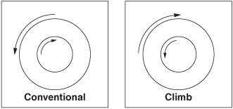
This option tells your CAM output to have your cutter travel from left to right, or from right to left. This does not initially sound like such an important selection to make; however, it is of paramount in importance when CNC milling! If you have ever used a hand-held router before, odds are you are already familiar with what the proper direction of travel is: inside profiles go clockwise and outside profiles go counterclockwise. This orientation of direction is what is referred to in CNC terms as conventional milling. Then, what is climb milling? It’s the reverse of conventional milling (Fig. 9-7). Again, if you are familiar with using a hand-held router, you may know this as back routing.
The reasoning behind having the ability to select either type of milling is simply a matter of how the finished edge of the material will appear. For example, most types of wood and wood composites will end up looking the best when a conventional direction is employed. Yet, there are many plastics and metals that look best when climb milling is used. Many of the bit-specific parameters you will need have already been derived for you.
Note that the direction (clockwise or counterclockwise) will always be opposite of the other for interior versus exterior types of profiling.
Step-Over
This option is mainly used in conjunction with area clearing. Parameter options typically allow the user to indicate a specific incremental amount and also a percentage of step-over. Most users will initially want to have their step-over at its maximum for efficiency, but this is not always the case. Depending upon your machine, you stand the chance of leaving behind “fins” of unmilled material. Also, because of corner rounding, you too will leave behind material when performing square or rectangular pocketing routines. From experience, I tend to leave my step-over amount in the 50% range, but for another reason as well. Since your bit will only be removing one-half of its normal amount of material, you can greatly increase the cut feed rate as well as help extend your cutter’s wear life.
Step-Down
Depending upon material type, cutter diameter being used, feed rate, etc., you will often find times when making a full-depth pass to cut your part is not achievable. A good example of this would be the cutting some ¼-in plywood versus cutting some 2-in-thick maple hardwood. This is where the cutter “step-down” option is used. Depending upon your CAM software, there will be differing options available for you to choose from. A general rule of thumb is to select a step-down amount that is equal to or less than the diameter of the cutter bit you are using. In the case of the 2-in-thick maple, if you have chosen a ¼-in bit for the task, it could take as many as eight passes for a profile cutout. In addition, there are times when the user wants the cleared area (during an area-clearance routine) that is left visible to end up with a finish that is as nice as possible. What can be done to achieve this is to perform a final clearance path that removes as little material as possible. This way the forces exerted on the cutter are minimized with little material to remove.
Another useful task of this feature is to only remove a thin amount of material on the final cut out pass. This helps reduce the cutting forces that are exerted on the part just prior to its removal from the sheet stock.
Finish Profiling
During repeated cutter step-downs on some material, slight ridges, which are undesirable, will be left visible on the profile. What the user can do to eliminate the stepped lines is to establish all the initial and/or step-down passes a very slight amount, oriented to the outside of the final vector path. Furthermore, the user should ensure that the final “roughing” pass does not completely cut through all of the material, but the part is left in place by a thin skin of material. The final pass of the cutter bit should then precisely cut up to the vector boundary line, as well as be set for a final depth to cut the part out.
Ramped Entry Cut
In order to cut out parts of a piece of material, the cutter bit needs to be “plunged” by some method into the material at the starting point (numerous times if using step-down). However, not all router bits and materials work well together during the straight-down plunging process. Setting up a ramped entry is many times the viable solution to help alleviate your ending up with an elongated hole that can show up in the final profile of the part. What this type of entry cut does is saw its way sideways parallel to the vector path until the desired step-down depth for the particular pass is met. This reciprocating action uses the cutter’s side-milling ability to do the majority of the work, rather than just the tip of the cutter.
Lead In/Lead Out
This is yet another widely used option that can greatly help in eliminating the typical entrance/exit cutter marks that are produced from profile cuts. This feature allows the user to establish a bit entrance point that is some distance away from the actual vector path. Once the cutter is at the desired cutting depth, the bit is then lead into the associated vector path. Upon completing the milling of the part, the bit can then be optionally lead out of the vector path prior to being retracted. There also is typically an optional user-defined distance where the lead-out position will purposely overlap the initial lead-in position. This virtually eliminates profile marks left behind from plunging cuts. Note that this feature can also be used in conjunction with step-downs and cutter ramping.
Part Tabbing
Invariably there will be times when the user lacks the ability to safely hold the parts down to the table or it may also be desired to leave parts slightly held in place after the machining process is complete. Tabbing is a nice feature to use, which is especially important to stop your parts from flying off the table once the cutting is complete. How this is accomplished is by intentionally leaving behind small thin tabs of material after milling is completed. Once the milling operation is finished, the entire sheet of material can be removed from the spoil board and the parts “popped out.” Quick sanding of the area where the tab was located is generally all that is needed to finish the part.
Nesting
Many CAM programs will allow the user to take a single (or multiple) part and replicate it multiple times on the size of the sheet material. In conjunction with this, the user can have the CAM program nest the parts to help minimize the overall amount of material needed. You will typically find options, such as number of times to replicate, along with spacing between the parts and the rotation origination. If you are working with a material that has a grain or working direction, the manner in which each part is oriented can become a key factor when being nested. If your work necessitates multiples of the same part to be cut from sheet stock, this is one feature you may find beneficial. It plays a major role in the amount of material ordered and in pricing.